16x2 lcd fails to intialize from time to time

Thread Starter

Anirban Raha

Joined Dec 4, 2013
70
Hi! I'm using a AT89s52 and 16x2 LCD display(JHD 162A) in 8 bit mode. The problem is, when I power up my circuit, the LCD, sometimes does not display anything except black boxes on the first line. Other times, it is working fine. Does this mean that sometimes my LCD is not being initialized properly? This is happening on a breadboard, a perf-board, and also on a dev board(http://exploreembedded.com/wiki/8051_Ultra_Development_Kit) that I have recently purchased. Why is this happening? Can someone please help!

Code:
#include<reg52.h>                             //including sfr registers for ports of the controller
#include<lcd.h>

//LCD Module Connections
sbit RS = P0^0;                                                                  
sbit EN = P0^1;                           
sbit D0 = P2^0;
sbit D1 = P2^1;
sbit D2 = P2^2;
sbit D3 = P2^3;
sbit D4 = P2^4;
sbit D5 = P2^5;
sbit D6 = P2^6;
sbit D7 = P2^7;
//End LCD Module Connections
void Delay(int a)
{
    int j;
    int i;
    for(i=0;i<a;i++)
    {
        for(j=0;j<100;j++)
        {
        }
    }
}
void main()
{
    int i;
    Lcd8_Init();                                 
  while(1)
  {                                  
    Lcd8_Set_Cursor(1,1);
      Lcd8_Write_String("TEST");
    }
}
The header file lcd.h :

Code:
//LCD Functions Developed by electroSome

//LCD Module Connections
extern bit RS;                                                                  
extern bit EN;                          
extern bit D0;
extern bit D1;
extern bit D2;
extern bit D3;
extern bit D4;
extern bit D5;
extern bit D6;
extern bit D7;
//End LCD Module Connections


void Lcd_Delay(int a)
{
    int j;
    int i;
    for(i=0;i<a;i++)
    {
        for(j=0;j<400;j++)
        {
        }
    }
}

//LCD 8 Bit Interfacing Functions
void Lcd8_Port(char a)
{
    if(a & 1)
        D0 = 1;
    else
        D0 = 0;
   
    if(a & 2)
        D1 = 1;
    else
        D1 = 0;
   
    if(a & 4)
        D2 = 1;
    else
        D2 = 0;
   
    if(a & 8)
        D3 = 1;
    else
        D3 = 0;
   
    if(a & 16)
        D4 = 1;
    else
        D4 = 0;

    if(a & 32)
        D5 = 1;
    else
        D5 = 0;
   
    if(a & 64)
        D6 = 1;
    else
        D6 = 0;
   
    if(a & 128)
        D7 = 1;
    else
        D7 = 0;
}
void Lcd8_Cmd(char a)
{
  RS = 0;             // => RS = 0
  Lcd8_Port(a);             //Data transfer
  EN  = 1;             // => E = 1
  Lcd_Delay(5);
  EN  = 0;             // => E = 0
}

Lcd8_Clear()
{
      Lcd8_Cmd(1);
}

void Lcd8_Set_Cursor(char a, char b)
{
    if(a == 1)
      Lcd8_Cmd(0x80 + b);
    else if(a == 2)
        Lcd8_Cmd(0xC0 + b);
}

void Lcd8_Init()
{
    Lcd8_Port(0x00);
    RS = 0;
    Lcd_Delay(200);
    ///////////// Reset process from datasheet /////////
  Lcd8_Cmd(0x30);
    Lcd_Delay(50);
  Lcd8_Cmd(0x30);
    Lcd_Delay(110);
  Lcd8_Cmd(0x30);
  /////////////////////////////////////////////////////
  Lcd8_Cmd(0x38);    //function set
  Lcd8_Cmd(0x0C);    //display on,cursor off,blink off
  Lcd8_Cmd(0x01);    //clear display
  Lcd8_Cmd(0x06);    //entry mode, set increment
}

void Lcd8_Write_Char(char a)
{
   RS = 1;             // => RS = 1
   Lcd8_Port(a);             //Data transfer
   EN  = 1;             // => E = 1
   Lcd_Delay(5);
   EN  = 0;             // => E = 04
}

void Lcd8_Write_String(char *a)
{
    int i;
    for(i=0;a[i]!='\0';i++)
     Lcd8_Write_Char(a[i]);
}

void Lcd8_Shift_Right()
{
    Lcd8_Cmd(0x1C);
}

void Lcd8_Shift_Left()
{
    Lcd8_Cmd(0x18);
}
//End LCD 8 Bit Interfacing Functions

//LCD 4 Bit Interfacing Functions

void Lcd4_Port(char a)
{
    if(a & 1)
        D4 = 1;
    else
        D4 = 0;
   
    if(a & 2)
        D5 = 1;
    else
        D5 = 0;
   
    if(a & 4)
        D6 = 1;
    else
        D6 = 0;
   
    if(a & 8)
        D7 = 1;
    else
        D7 = 0;
}
void Lcd4_Cmd(char a)
{
    RS = 0;             // => RS = 0
    Lcd4_Port(a);
    EN  = 1;             // => E = 1
  Lcd_Delay(5);
  EN  = 0;             // => E = 0
}

Lcd4_Clear()
{
    Lcd4_Cmd(0);
    Lcd4_Cmd(1);
}

void Lcd4_Set_Cursor(char a, char b)
{
    char temp,z,y;
    if(a == 1)
    {
      temp = 0x80 + b;
        z = temp>>4;
        y = (0x80+b) & 0x0F;
        Lcd4_Cmd(z);
        Lcd4_Cmd(y);
    }
    else if(a == 2)
    {
        temp = 0xC0 + b;
        z = temp>>4;
        y = (0xC0+b) & 0x0F;
        Lcd4_Cmd(z);
        Lcd4_Cmd(y);
    }
}

void Lcd4_Init()
{
    Lcd4_Port(0x00);
    Lcd_Delay(200);
    ///////////// Reset process from datasheet /////////
  Lcd4_Cmd(0x03);
    Lcd_Delay(50);
  Lcd4_Cmd(0x03);
    Lcd_Delay(110);
  Lcd4_Cmd(0x03);
  /////////////////////////////////////////////////////
  Lcd4_Cmd(0x02);   
    Lcd4_Cmd(0x02);
  Lcd4_Cmd(0x08);    
    Lcd4_Cmd(0x00);
    Lcd4_Cmd(0x0C);    
  Lcd4_Cmd(0x00);   
  Lcd4_Cmd(0x06);  
}

void Lcd4_Write_Char(char a)
{
   char temp,y;
   temp = a&0x0F;
   y = a&0xF0;   
     RS = 1;             // => RS = 1
   Lcd4_Port(y>>4);             //Data transfer
     EN = 1;
     Lcd_Delay(5);
     EN = 0;
     Lcd4_Port(temp);
     EN = 1;
     Lcd_Delay(5);
     EN = 0;
}

void Lcd4_Write_String(char *a)
{
    int i;
    for(i=0;a[i]!='\0';i++)
     Lcd4_Write_Char(a[i]);
}

void Lcd4_Shift_Right()
{
    Lcd4_Cmd(0x01);
    Lcd4_Cmd(0x0C);
}

void Lcd4_Shift_Left()
{
    Lcd4_Cmd(0x01);
    Lcd4_Cmd(0x08);
}
//End LCD 4 Bit Interfacing Functions
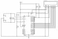
The circuit is a standard interface between AT89s52 and 16x2 LCD with R/W grounded, Port P2 connected to D0-D7, P0.0 = RS, P0.1 = E of LCD. Contrast has been set using a 10k pot with Vee to Vss resistance set to 1.5kohm.
 

Thread Starter

Anirban Raha

Joined Dec 4, 2013
70
Try delaying a whole second after powerup before talking to the LCD at all.
Tried. Same thing happening. However, I have made another observation. If I press the reset button connected to the RST of my uC, the LCD displays correctly. Any explanations?
 

Art

Joined Sep 10, 2007
806
That would be my next suggestion. You haven’t said what speed the micro is clocked.

If all else fails you could do a hardware delay, but always preferable to find the problem.


Delays between commands to LCDS might not be long enough.

Also post your schematic.
 

absf

Joined Dec 29, 2010
1,968
Port 1,2,3 has internal pullups while port 0 has open-drain outputs. Did you put pullup resistors on the EN and RS lines?

Allen
 

Thread Starter

Anirban Raha

Joined Dec 4, 2013
70
Delays between commands to LCDS might not be long enough.

Also post your schematic.
I've tried increasing delays to several seconds...didn't make any difference except making things slower when it's working. The schematic attached is of my perf-board. It does not have a reset button and thus the circuit works only occasionally. My dev board has a reset button. In my dev board, I need to press the reset button in case its not working just by turning on power. Do LCDs have some sort of exit mechanism? I mean, do I need to clear its registers before switching off power or something?
Please find attached schematic.
 

Attachments

Thread Starter

Anirban Raha

Joined Dec 4, 2013
70
Port 1,2,3 has internal pullups while port 0 has open-drain outputs. Did you put pullup resistors on the EN and RS lines?

Allen
Yes. Without the pull ups, the LCD displays nothing(blank). This is happening after adding the pull ups.
 

takao21203

Joined Apr 28, 2012
3,702
Here's the solution. I have used them sometimes, and of course, random not-functioning at startup cant be accepted for professional circuit at all.

Its simple. Power up the LCD through port IO. These LCDs dont like slowly rising supply voltage.
After that, wait some time.

Also add at least 20% to the delay time from the datasheet.

On the internet there are some shortened initializations, which are incorrect, and may not work for 4 bit at all, or not on all displays. The correct method is complicated and lengthy.

You can find info here: http://elm-chan.org/

You can also use them at 3 volts, just the LCD bias needs to be slightly higher than that, and the delays must be much longer.
 

Art

Joined Sep 10, 2007
806
Lol It could be a problem, but tjen it shouldn't be solved by reset.
They are such trash it might not work if the micro was slowed down.
 

Art

Joined Sep 10, 2007
806
Oh my, it might be that the micro is started in beat with the LCD cpu to get the bits of the port all set in time, or not.
 

JohnInTX

Joined Jun 26, 2012
4,787
One problem could be that E is pulled up. During RESET, E will be '1' and the LCD could take transitions on the port as commands - putting it into some unknown state.. Relocate E to a push-pull output and add a pull-down.

Hitachi calls out a 15ms delay after Vcc rises to 4.5V (40ms after 2.7V). You don't need to power it off a port.

Lcd8_Port( ) and Lcd4_Port( ) are trash.
It's so that the data bus lines can go to arbitrary port pins. Usually not necessary.

EDIT for TS: Here's the Hitachi 44780 datasheet that will answer questions about delays, inits etc.
 

Attachments

Last edited:

Art

Joined Sep 10, 2007
806
I forgot you have to pull a pin to get it to read the port.
Otherwise I would have pointed out what happens if the LCD reads while the micro is part way through writing the port :D

That not being the case, if you were going to address bits individual it’s still a waste of time & memory
Code:
//LCD 8 Bit Interfacing Functions
void Lcd8_Port(char a)
{
D0 = 0; // or clear the whole port
if(a & 1) {D0 = 1;}

bla bla...
One problem could be that E is pulled up. During RESET, E will be '1' and the LCD could take transitions on the port as commands - putting it into some unknown state.. Relocate E to a push-pull output and add a pull-down.

Hitachi calls out a 15ms delay after Vcc rises to 4.5V (40ms after 2.7V). You don't need to power it off a port.

It's so that the data bus lines can go to arbitrary port pins. Usually not necessary.
 
Last edited:

JohnInTX

Joined Jun 26, 2012
4,787
Thinking more about delays. The code makes no mention of the uC's oscillator frequency which will affect delays. It also does not calibrate delays to the oscillator freq - it just passes unscaled ints to a counter. If the oscillator is not what the code expects, the delays will be off.

Note that the commands for Return Home and Clear Display take WAY longer to execute than the others. Hitachi says 1.52ms for Return Home and does not spec a time for Clear Display (but I can tell you, it takes a long time.) Another datasheet from OPTREX I have using the 44780 at the same internal frequency calls out 15.2ms for both. ??? This code does not automatically take these extra times (whatever they are) into account. Even if it did, different displays may run at different internal frequencies.

Because of the uncertainty, I've always polled the BUSY flag in the 'send byte to LCD' routine just before I need to write the next character and wait there if necessary. An alternate way without the BF would be to set a timer to the time appropriate to the instruction just after doing it then check the timer before the next operation. If its been long enough since the last write, there's no sense in waiting. The WORST option is to have to monkey with LCD instruction-dependent delays in your code flow and have to remember that clearing the display takes longer etc.

You can also avoid the long clearing process by 1) manually writing 20h (space) to only the visible characters - Clear Display clears the entire character RAM one byte at a time or 2)my favorite, just pad each line to the display width and always write 16 or 20 characters as required to overwrite what's currently on the screen.

Good luck.
 

MrChips

Joined Oct 2, 2009
30,821
+1
What John says. I poll the busy flag before sending.
Instead of clearing the display I send 16 spaces to the line I am writing to.
 

takao21203

Joined Apr 28, 2012
3,702
One problem could be that E is pulled up. During RESET, E will be '1' and the LCD could take transitions on the port as commands - putting it into some unknown state.. Relocate E to a push-pull output and add a pull-down.
That might be part of the problem. If you power it off, set all to zero, then power on, you get rid of all possibilities.

Hitachi calls out a 15ms delay after Vcc rises to 4.5V (40ms after 2.7V). You don't need to power it off a port.
Its the most effective way of dealing with the problem. There are chips with so many small pins- why not use a few now and then?

[
It's so that the data bus lines can go to arbitrary port pins. Usually not necessary.
Its akward to do it like that. Normally, its done with tables- one entry for the port address, another 2 for setting/resetting mask. If it is just a bit or two, can first write wrong value to buffer then correct it.

Its hard to use these displays correctly- basically, you need a contrast potentiometer, and a constant voltage, to take care the startup, delays which could be longer depending on temp., and age.
With the charge pump you need at 3v, a graphical LCD is cheaper, and not riddled with delays so much (basically they are faster than any small MCU software serial port).

EDIT for TS: Here's the Hitachi 44780 datasheet that will answer questions about delays, inits etc.
 

JohnInTX

Joined Jun 26, 2012
4,787
Its the most effective way of dealing with the problem. There are chips with so many small pins- why not use a few now and then?
If you compare the LCD current requirements with the current source capabilities of the Atmel part, you'll see that a single pin is going to have problems driving the LCD display at anywhere near Vcc. The other problem is that even if you are lucky enough to get the current (its not guaranteed) the lightly loaded data outputs are likely to present a greater voltage than Vcc provided by the heavily loaded power source pin. The CMOS 44780 won't like that.

Its akward to do it like that. Normally, its done with tables- one entry for the port address, another 2 for setting/resetting mask.
True enough but you'll find that all of that table access will generate more code than the method described. But I am not advocating doing it either of those ways, just pointing out that this particular library takes care of arbitrary pin assignments by bit-flipping to make it more general. Personally, I don't use LCD libraries, preferring my own code.

As far as using other displays, that's up to the TS. He asked about Hitachi 16x2
 

takao21203

Joined Apr 28, 2012
3,702
If you compare the LCD current requirements with the current source capabilities of the Atmel part, you'll see that a single pin is going to have problems driving the LCD display at anywhere near Vcc. The other problem is that even if you are lucky enough to get the current (its not guaranteed) the lightly loaded data outputs are likely to present a greater voltage than Vcc provided by the heavily loaded power source pin. The CMOS 44780 won't like that.
Questionable for me. These LCDs need 1mA or less that's why people like them, can run long time from battery. Thats also the reason for the low clocking frequeny. A potential of o.2v or so through a high-impedance IO structure wont harm CMOS. I doubt its happening, it will sag down the rest of the port, but as I said, these Hitachi LCDs are very conservative in terms of using power.

True enough but you'll find that all of that table access will generate more code than the method described. But I am not advocating doing it either of those ways, just pointing out that this particular library takes care of arbitrary pin assignments by bit-flipping to make it more general. Personally, I don't use LCD libraries, preferring my own code.

As far as using other displays, that's up to the TS. He asked about Hitachi 16x2
Sure its his choice, I just mention that it is hard to get everything right with these. Always powering up correctly one such requirement.

Sure the tables arent fast, and would generate 100s of program words. But lately there's so much FLASH available. Its better if you need to change the source again and again, just define one set of const arrays, than to change the actual code. It can automatically configure Tristate too.

At 3 volts these Hitachi modules arent bad, little current is needed.

I have often programmed eco modes, which flash LED light or pheripherals to some complicate chopping algorithm, so you could use the battery much longer.
 
Top