16-bit Binary to Decimal

BillB3857

Joined Feb 28, 2009
2,570
I also don't understand the difference between binary and BCD. I thought that was the same thing.

That's it.

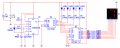
BCD is a form of binary that is limited to ten counts and represented by 4 binary positions (1,2,4,8). A BCD counter will have internal gates that detect the tenth count and strap back to reset the chip and start counting again from zero. A BINARY counter (the one you have) does not have the internal gate arrangement and simply ripples through all 16 possible states that can be represented by 4 bits.
 

Thread Starter

hondabones

Joined Sep 29, 2009
123
Right, I new it did some kind of ripple... I'm still researching on all that to see if I can figure out what it means.

It's my understanding that you add the bits from right to left

1100 is 12. 0 + 0 + 4 + 8

For the 7493 if you label the bits respectively D, C, B, A (pins: Qd, Qc, Qb, Qa)
the out put counts down in binary.

The internals are a mod-2 and mod-8, by tying Qa to ClkB I get mod-16. I tried to simulate just the mod-8 so I can just use one 7seg display but my simulation software won't cooperate so I am unsure if I am doing it right. You can also get a mod-9 out of it which will essentially use all 10 decimal digits on one 7seg.

BillB3857 I still don't get BCD. I have a (I think) 7490 which is a decade counter. Very similar to the 7493 but the internals are a mod-2 and mod-5 which I think only goes up to 10 (hence decade counter).

I have a CD4511 coming in the mail. From what I understand it will except 4-bit binary and output the correct decimal digit on a single 7-seg cathode display. So I need to figure out out to get the other 6 decimal digits 10 - 15.

This has definitely been one of my best learning projects and I can't thank you guys enough for your help. I have been building silly LED, IR and motion detection circuits and this one has been the most beneficial. Unfortunately I won't learn this stuff for two more quarters.
 

BillB3857

Joined Feb 28, 2009
2,570
Converting from one number system to another is sometimes quite complicated. Go to the top of this page and click on Vol IV. Read through chapter one for a better understanding of number systems and how they relate and don't relate to each other.
 

Thread Starter

hondabones

Joined Sep 29, 2009
123
Converting from one number system to another is sometimes quite complicated. Go to the top of this page and click on Vol IV. Read through chapter one for a better understanding of number systems and how they relate and don't relate to each other.
That was a lot of information to take in. I get how it all works now.

Let me just clarify:

BCD represents each decimal digit with 4 bits.

e.g.

100002 is 1610

for BCD

00012 01102 is 1610
 

BillB3857

Joined Feb 28, 2009
2,570
That was a lot of information to take in. I get how it all works now.

Let me just clarify:

BCD represents each decimal digit with 4 bits.

e.g.

100002 is 1610

for BCD

00012 01102 is 1610
YES!!
(after re read--- see my DUHHHHH at the end)
1610 in BCD would be 0001 0110 0001 0000 (one group of 4 bits per decimal digit)

1610 in pure BINARY would be 11001001010

Do you use Microsoft Windows? If so, use their scientific calculator and you can put a number into it in HEX, OCTAL, DECIMAL or BINARY by selecting the base you want to imput and simply select the other base you want to convert it to and it will display the converted representation.

DUHHHHHH> I just looked again at your post. The 2's you show represent the Base 2 or binary as well as the 10 after 16 representing base 10 or decimal so YES, your conversion is correct. The number you show is NOT One Thousand Six Hundred Ten but Sixteen, base 10
 

Thread Starter

hondabones

Joined Sep 29, 2009
123
Do you use Microsoft Windows? If so, use their scientific calculator and you can put a number into it in HEX, OCTAL, DECIMAL or BINARY by selecting the base you want to imput and simply select the other base you want to convert it to and it will display the converted representation.
No kidding? I use this PC for 90% of my circuit experiments before actually proto-typing. That is an awesome feature.

DUHHHHHH> I just looked again at your post. The 2's you show represent the Base 2 or binary as well as the 10 after 16 representing base 10 or decimal so YES, your conversion is correct. The number you show is NOT One Thousand Six Hundred Ten but Sixteen, base 10
Yes. I actually did take your advice and read the E-Book section you suggested. The base units are how you distinguish between the different number types. I learned well! In part from you. Thanks for the lesson.
 

Thread Starter

hondabones

Joined Sep 29, 2009
123
I got my 4511 chip today. I went through the tutorial here on the site for the 7-segment and the 4511 so I could get familiar with the chip. I hooked it up to the circuit and after a bit of trouble shooting I was able to get a count from the 7-seg. I converted the circuit to a mod-8 just for experiment purposes. Plus I don't have the dual 7-seg yet. The only problem I have now is the display is counting, but it isn't showing the digits correctly. I will have to figure that out. When I have the opportunity I will post the current circuit for you guys to see. I am sure you will find the mistakes. I know I'm in way over my head at this point in my studies. I am learning though. :)
 

BillB3857

Joined Feb 28, 2009
2,570
Just hang in there, Hondabones. Making mistakes along the way, believe it or not, helps the learning process. By your circuit not working exactly as planned, it is forcing you back to the search for more information. That's a good thing!.
 

Thread Starter

hondabones

Joined Sep 29, 2009
123
I will hang in there. I'm afraid though I will have to put this one on the back burner for now. I will draw up the schematic though.
 

Thread Starter

hondabones

Joined Sep 29, 2009
123
Here's the schematic as it is on the board. LED1 is actually not connected because it is not used for mod-8 on the 7493. I changed how it counts so I could use the single 7-Segment rather than the dual 7-segment.

The binary display (3 LEDs) counts perfectly from 7 - 0 and keeps recycling the count.

In the picture the decimal display reads 7. That's not correct because I attempted to simulate the circuit in MultiSIM. MultiSIM doesn't normally act right when I incorporate very many LEDs into the simulation. (I think my PC is too slow)

In real life the decimal display flickers a lot and the displayed number also is not readable. I checked and rechecked the pinout and I believe it is 100% correct so the 4511 isn't turning on the correct LEDs for the display. If I left anything out or you have questions on the schematic just ask, I am eager to learn.


Attachments

Last edited:

BillB3857

Joined Feb 28, 2009
2,570
Just a few questions.... Is the 7 segment a common Anode type? You do have ground of the 7 segment connected, right? Why all the different values for current limit resistors? Are you sure you have the outputs of the 4011 connected to the proper segments of the display?
 

Thread Starter

hondabones

Joined Sep 29, 2009
123
Is the 7 segment a common Anode type? You do have ground of the 7 segment connected, right?
It is a common cathode. yes it is connected.
Why all the different values for current limit resistors?
I have limited parts. I assumed it would only effect the LED brightness. So I didn't consider that an issue.
Are you sure you have the outputs of the 4011 connected to the proper segments of the display?
It is a 4511. Yes, I checked and rechecked the outputs.

I see a few things I want to look at.

Let me get back to you on this question.
 

Thread Starter

hondabones

Joined Sep 29, 2009
123
o.k. I think my display is dead.

I hooked up the dual 7-seg. This component is common anode. This chip's data sheet shows the two digits wired together. i.e. if I hook up both, they both will count simultaneously (88, 77, 66 etc.) I hooked up one and I get a single digit counting.

One problem: The 4511 only uses common cathode displays. I noticed, however, that the parts of the display that were off displayed a number. The count went like this:

0, 2, 4, 6, 1, 3, 5, 7, and starts over.

During my experiments I disconnect the power and try a few different hook ups between the 7493 out and the 4511 in and I in turn mess up the display. Almost like something needs to reset. I can't figure out how I fix the problem but eventually I end up with the same count as mentioned above. It's consistent and correct. Just not chronological.

I'm off to find a common cathode display. This should be my first fix in troubleshooting this. I need the correct components. lol.
 

BillB3857

Joined Feb 28, 2009
2,570
Good observation that the OFF segments were counting rather than the ON segments. A for the 0, 2, 4, 6,1, 3, 5, 7 counting, My bet is on having a couple of the lines switched between the counter and decoder. You WILL get it figured out! It's all part of the fun in the learning process. Make yourself a truth table of the binary count, then find what combination's give the sequence you are seeing. It will then be apparent to you.
 

Thread Starter

hondabones

Joined Sep 29, 2009
123
I found a common cathode display.

I don't really know how how to make a truth table. I do understand what you are asking me to do though. If binary display is 000 check the corresponding decimal display. Write down all the combinations and the pattern should be realized, correct?
 

Thread Starter

hondabones

Joined Sep 29, 2009
123
JACKPOT!!!

The 4511 doesn't except 3-bit binary. So I wired it up as 4-bit and it is counting from 0 - 15.

0 - 9 displays as it should 10 - 15 do nothing.

What through me off is the LEDs representing the binary numbers are showing the correct numbers on the OFF LEDs.

So...

1111 (on, on, on, on) is not 15, it's 0
0001 (off, off, off, on) is not 1, it's 14
etc.
 

Thread Starter

hondabones

Joined Sep 29, 2009
123
I was under the impression the LEDs from the 7493 had to go to +6 V.

I turn them around and sent the to the negative rail and I get the correct count visually. (on LEDs display the binary)

Now to hook up the new common cathode display so the decimal display is showing correctly.

This experiment has been a complete success.

Thank you BillB3857!

This has been a wonderful learning experience.

Thanks also to all who replied and contributed to my experiment.
 

BillB3857

Joined Feb 28, 2009
2,570
WAY TO GO!!! I knew you could do it. And you learned much more by figuring it out with just a few nudges. Scratching your head when it doesn't itch also helps.
 

Thread Starter

hondabones

Joined Sep 29, 2009
123
A little update:

Remember I had that 7493 chip that I original started with? I replaced it with a 7490 which is a decade counter. So I have a perfect count 0-9.

Then I thought: Let's count to 99...

So I figured out how to get the 7493 to reset at 10. So instead of counting 0 - 15, it now counts 0 - 9.

I wired them together along with another 4511 and 7-segment and vuala! 0 - 99

It's starting to come second nature to me, now. My next project: TTL Clock.
 
Top