Thank you all for your help.
when i get back into town i will order the other (right) parts, for now i will use the quick fix. if i do manage to get it all working i will leave a link for the video.
I don't think a 7812 will work but a 317, which has a 1.2V drop-out, might. 12V in, 10.8V out. I think there is a good chance that the camera will work on 10.8V.
OK, to more directly address this...
The 78xx series of regulators are actually fairly similar to the 117/317 series regulators. A few differences are:
1) They have R1/R2 internal, rather than requiring externally connected R1/R2.
2) The tab is connected to GND instead of VOUT (understandable, as a 117/317 has no direct connection to GND).
3) They are rated for 1A vs 1.5A.
It's common knowledge that the voltage output of a 78xx regulator can be increased by adding resistance between the devices' GROUND terminal and actual ground; however this also requires isolation of the tab from ground.
Back of an envelope moment. The attached circuit should also work. The output will pretty much track the input but will not exceed around 11.8V.
While the circuit is a novel idea and may in fact be viable, I have not had time to so much as simulate it, our OP is not as experienced as we are, and is completely out of time.
All things considered, the 78xx series regulators are most certainly not the most desireable approach; however I feel it is the most viable at this point.
78xx series regulators have been widely used for 30+ years, and are quite reliable if utilized within their specifications. They were well-engineered devices for their time. They have built-in thermal protection, current limiting, etc. which your "napkin drawing" schematic may not provide; I don't know yet as I have not had the chance to simulate it. As of this moment, I don't even have your specifications for transistors to be used for simulating it - however, if Radio Shack doesn't have it in stock, it is not likely to be available to our OP.
This is one of those situations where a "minimal risk" path must be followed.
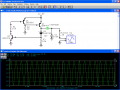
Blocco, I simulated your circuit using basically what I had available in this limited PSPICE simulator vs what Radio Shack might have available.
The only thing I can't really get specs for is the only possibly suitable PNP pass transistor that Radio Shack stocks, which they call a TIP42G, but they say it's actually an MJE34 - of course, I can't find a manufacturer's datasheet for that part number anywhere.
It seems to work pretty well, even with the 2N3904/2N3906 transistors. Changing those to 2N4401/2N4403 helps improve regulation. With a 10uF cap on the output, the 2N3904/2N3906 allowed about 14mV swing between minimum/maximum load, the 2N4401/2N4403 dropped that down to under 11mV.
Radio Shack doesn't carry an 11.1v Zener, just 5.1 and 12v, but using the 12v Zener the simulation gave 12.34v out. As that's within 3% of 12v, it's certainly good enough.
However, until I could actually test it with that TIP42G that RS carries, I can't say for certain how well it would actually work.
I made a slight amendment, which is to put a 10k resistor in series with the base of Q2. It doesn't need it for the circuit to work but would protect Q2 against current being fed back into the regulator from a reactive load.
Q3 could be just about any PNP power transistor with an hFE of around 100 or more. I haven't thought much about optimising the circuit performance in terms of regulation as the camera will have its own regulators.
I made a slight amendment, which is to put a 10k resistor in series with the base of Q2. It doesn't need it for the circuit to work but would protect Q2 against current being fed back into the regulator from a reactive load.
That's the problem I'm facing at the moment - the TIP42G/MJE34 that Radio Shack carries has no hFE specifications listed. "real" TIP42's have an hFE of between 15 and 75, according to Motorola (TIP41A/D datasheet)
Ahhh... the "G" suffix means lead free. Finally, that little dim bulb starts glowing... leave it to Radio Shack to leave out the A/B/C specification, but include the lead free spec.
Still, the actual parts have "MJE34" inscribed on them, and I just can't find a datasheet. MJE340's are very different.
The 2N4407 I used in the simulation has an ideal maximum forward beta of 208. I don't think the Radio Shack version of a TIP42 will come anywhere close to that; and this transistor is the only PNP they carry with a high enough current (6A) and wattage (65W) rating. Were I to make a wild guess, I'd say their TIP42G with a 500mA load might have an hFE around 40, or less than half of what you say the circuit needs.
Now if they'd carried something like an IRF9Z24 (P-ch power MOSFET) we could've done something with that - but like most everyone knows, RS's selection of components is painfully limited nowadays.
I haven't thought much about optimising the circuit performance in terms of regulation as the camera will have its own regulators.
Well, it's really not bad at all as it is. However, the simulation of the Zener is quite suspect; normally for a 1W Zener you'd need to get around 20mA through it in order to enter the linear regulation region. As the circuit is now, Zener current is 60uA; far below what's necessary. If I measured a real 1N4742 12v Zener, I'm sure the readings would be quite different.
Dropping R3 from 10k to 30 Ohms puts Zener current in the ballpark, but of course that causes Vout to increase to around 12.6v - too much.
It may be that the only "Radio Shack" option would be to use several LEDs in series, with perhaps 3ma to 5mA flowing through them to provide something of a stable reference.
R2 can always be reduced to 470 Ohm to compensate for lack of hFE in Q3, currently (and currently) it has around 10mA but I just wanted to make sure it had enough base current to keep it on under full load plus a bit extra.
Incidentally, a revealing test for real voltage regulators is to switch the full load on and off with a square wave as it shows how fast the regulator responds to sudden changes in load and can be very useful for tweaking purposes.
sgt wookie
the plan has changed. i am now only needing to go from 13.8 - 12.0 volt down to 5 volts at 2 amps. this is what i have so far, nte-1934x . was going to use there diagram off the net. http://www.nteinc.com/specs/1900to1999/pdf/nte1934x.pdf
whats your thoughts on this setup. also power use isnt so much an issue.
thank you again.
You could use that, but NTE parts are normally many times more expensive than the original parts their product is supposed to replace. The max 15v input is of concern; automotive environments are brutal. It would not be hard to exceed the NTE part's input voltage.
You would do better with a National Semiconductor LM350, which is an adjustable 3A positive regulator. More current capability, higher allowable input voltage, and more stable as well. http://www.national.com/mpf/LM/LM350.html
Use a 120 Ohm resistor from the output terminal to the ADJ terminal (R1), and a 360 Ohm resistor from the ADJ terminal to ground (R2). Use caps on the input and output as shown on the National Semiconductor schematic.
i already purchased the nte ones and am leaving town friday. i will check tomorrow and see if that have the one local that you mentioned if not i will be stuck using the ones i bought.
thank you again
Make certain you use a large heat sink on whichever regulator you wind up with. Otherwise, it will overheat very rapidly. You're going to be dissipating 18 Watts of power in the regulator.
How I calculated power:
Nominal system voltage with engine running is 14v.
The regulator outputs 5v @ 2A
14v - 5v = 9v to drop across the regulator.
P = EI, or Power in Watts = Voltage x Current
P = 9v x 2A = 18W.
I suggest that you remove power to the input of the regulator prior to starting the engine, and leave it off until the engine has run for at least 10 minutes to recharge the battery. Otherwise, the system voltage may be high enough to kill your NTE regulator.
[eta]
I think that the NTE regulator could be a re-packaged KA278R05C, a Fairchild Semiconductor 2A 5V regulator. It's not in the NTE cross reference; as well it should not be, as it doesn't meet the input voltage specs - but the best I could come up with in the short period of time I've been looking at this thing.
The next time you ask for help two days before race day, I'll have two words for you.
"Good luck".
Your piss-poor planning in no way constitutes an emergency on my part. You knew this was coming up way ahead of time, and dragged your feet until the last minute, expecting a "save the day" miracle.
When the regulator goes Tango Uncle halfway through the race, and your team is left dead, you can thank yourself for your extreme lack of foresight, lack of ability to learn ANYTHING from your prior experience, and just overall stupidity.
Don't bother posting asking for advice on here anymore.

 Facebook
 Google
 GitHub
 Linkedin


 Finally, that little dim bulb starts glowing... leave it to Radio Shack to leave out the A/B/C specification, but include the lead free spec.




