120vac 1ph motor control

Thread Starter

Cholmes

Joined Apr 2, 2025
6
Hello All,
First off , I am not an electrical engineer in any shape or form so please be kind.
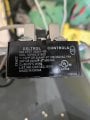
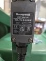
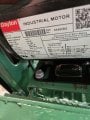
I have a bandsaw that has a 1ph , 120vac, cap start, cap run motor that I need a start/stop circuit. What I want to accomplish is that when I push a momentary push button the motor starts and stays running until the bow of the saw contacts a limit switch that stops the motor and resets the circuit. Then when I am ready to cut again, I push the start button and the cycle starts over. I would like to do it with relays so that it is simple to wire and maintain. Thanks for any help.
 

MaxHeadRoom

Joined Jul 18, 2013
30,557
K1 is a normally (N.O.) contact on the K1 relay .
It shows a typical stop/start string or E-stop circuit and N.C types of PB's or switches can be added to into the string , when the run contact is closed, the motor runs until any switch in the string opens, you can add other N.C devices as needed. e.g. bow saw contact SW.
 

LowQCab

Joined Nov 6, 2012
5,101
AKA, a "Safety-Loop", and a 2-Pole-Contactor set-up as a "Latching-Relay".

The Limit-Switch does not need to carry the full Motor-Current.
The Limit-Switch can be wired so that it is only breaking the power power going to the Contactor's-Coil.

K-1 is a "2-Pole-Motor-Contactor" rated for a 1-Horsepower-120V-Motor with a 120-Volt-Coil.
( minimum 20-Amp Contact-Rating, a 30-Amp-Rating is also just fine )

Do You need a revised Schematic-Drawing ?

Have You selected a "Limit-Switch" yet ?
.
.
.
 

MaxHeadRoom

Joined Jul 18, 2013
30,557
Any NC usually can be placed anywhere in the series string.
The representation/format is known mathematically as a NAND string in Boolean logic.
 

MisterBill2

Joined Jan 23, 2018
27,164
The first circuit, as posted, is incorrect BECAUSE the start button carries the full load current at the turn-on time. THAT is the flaw. Separate contacts to carry the load current are vital. In addition to the limit witch for automated stopping, there must also be a stop button.
 

Thread Starter

Cholmes

Joined Apr 2, 2025
6
AKA, a "Safety-Loop", and a 2-Pole-Contactor set-up as a "Latching-Relay".

The Limit-Switch does not need to carry the full Motor-Current.
The Limit-Switch can be wired so that it is only breaking the power power going to the Contactor's-Coil.

K-1 is a "2-Pole-Motor-Contactor" rated for a 1-Horsepower-120V-Motor with a 120-Volt-Coil.
( minimum 20-Amp Contact-Rating, a 30-Amp-Rating is also just fine )

Do You need a revised Schematic-Drawing ?

Have You selected a "Limit-Switch" yet ?
.
.
.
I'll send you the info on what I have for the switches, relays etc.
 

Thread Starter

Cholmes

Joined Apr 2, 2025
6
I'll send you the info on what I have for the switches, relays etc.
This is what I have. The motor is a Dayton 1 hp. The power relay is a Deltrol, the LS is Honeywell. I have attached pics of these. I also have a NO/NC MOM PB and an E-Stop button.

A revised sketch would be awesome.
 

Attachments

MisterBill2

Joined Jan 23, 2018
27,164
The photo of the motor tag with the connections was not taken at an angle that made the connections clear enough to provide useful information!!Way too much of an angle!
Please give us a straight on view, since for your application it seems that motor reversing is required, and the current view does not allow that part to be seen, but only guessed at.
 

Thread Starter

Cholmes

Joined Apr 2, 2025
6
The photo of the motor tag with the connections was not taken at an angle that made the connections clear enough to provide useful information!!Way too much of an angle!
Please give us a straight on view, since for your application it seems that motor reversing is required, and the current view does not allow that part to be seen, but only guessed at.
The motor doesn't need to reverse and it is wired for 115vac.
 
Top