1.8" color LCD (TFT)- any PIC code around?

Thread Starter

takao21203

Joined Apr 28, 2012
3,702
http://www.ebay.com/itm/1-8-Serial-SPI-TFT-Color-LCD-Module-Display-128X160-/200554112312

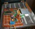
Have these around for a while and tonight have wired 18f24j10 together with one TFT display. All 3.3V technology. PIC LED is blinking so far.

The supplied example source is for 8051!

Has anyone ported the examples to PIC C already??

So this could save me some time on the weekend. Interface is serial.
I have all files here: Example sources, LCD connector PDF as well LCD controller PDF.

Power supply is 12V + MC34063 chip, down to 3.3V
 

Attachments

kingArgon

Joined Mar 20, 2011
33
its a SPI interface so just use the feature of the PIC or bit bang the data. pretty simple stuff.

maybe you can find some sample code at hackchina.com

good luck and happy hacking.
 

Thread Starter

takao21203

Joined Apr 28, 2012
3,702
its a SPI interface so just use the feature of the PIC or bit bang the data. pretty simple stuff.

maybe you can find some sample code at hackchina.com

good luck and happy hacking.
ST7753 controller. Yes hardware synchronous serial port will be used.

I have sample code here but for 8051, need to port this to PIC XC8.
 

Thread Starter

takao21203

Joined Apr 28, 2012
3,702
I have ported one of the example programs to XC8.
It works! Data transfer via bitbang is not so much phenomenal,
but I increased speed to about 5x by this:

Rich (BB code):
void LCD_DataWrite(unsigned char ch,unsigned char ch1)
{
lcd_cs=0;
lcd_rs=1;
 ch<<=1;lcd_sda=CARRY;lcd_scl=0;lcd_scl=1;
  ch<<=1;lcd_sda=CARRY;lcd_scl=0;lcd_scl=1;
   ch<<=1;lcd_sda=CARRY;lcd_scl=0;lcd_scl=1;
    ch<<=1;lcd_sda=CARRY;lcd_scl=0;lcd_scl=1;
     ch<<=1;lcd_sda=CARRY;lcd_scl=0;lcd_scl=1;
      ch<<=1;lcd_sda=CARRY;lcd_scl=0;lcd_scl=1;
       ch<<=1;lcd_sda=CARRY;lcd_scl=0;lcd_scl=1;
        ch<<=1;lcd_sda=CARRY;lcd_scl=0;lcd_scl=1;
lcd_cs=1;
lcd_cs=0;
 ch1<<=1;lcd_sda=CARRY;lcd_scl=0;lcd_scl=1;
  ch1<<=1;lcd_sda=CARRY;lcd_scl=0;lcd_scl=1;
   ch1<<=1;lcd_sda=CARRY;lcd_scl=0;lcd_scl=1;
    ch1<<=1;lcd_sda=CARRY;lcd_scl=0;lcd_scl=1;
     ch1<<=1;lcd_sda=CARRY;lcd_scl=0;lcd_scl=1;
      ch1<<=1;lcd_sda=CARRY;lcd_scl=0;lcd_scl=1;
       ch1<<=1;lcd_sda=CARRY;lcd_scl=0;lcd_scl=1;
        ch1<<=1;lcd_sda=CARRY;lcd_scl=0;lcd_scl=1;
        lcd_cs=1;

//LCD_DataWrite_IC(LCD_DataH);
//LCD_DataWrite_IC(LCD_DataL);
}
And I will see if it can improve further using the hardware serial port.
 

Thread Starter

takao21203

Joined Apr 28, 2012
3,702
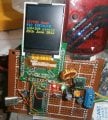
OK here a recent photo from the circuit.

I have changed the code to use hardware serial port as well.
And I want to move the font data into EEPROM!

Unfortunately pictures take more memory than the 18f24j10 has altogether,
so what I need is serial flash chips, and an interface to write data to them, for instance USB.

All I have here currently is 24LC256, means 32K EEPROM chips.
 

Attachments

Thread Starter

takao21203

Joined Apr 28, 2012
3,702
Rich (BB code):
void read16byte(unsigned char ind,unsigned char* buf)
{
    // start condition
    // write address (ctrl, slave akn, h addr, slave ckn, low addr, slave akn
    // start condition
    // ctrl word
    // slave akn
    // read 8 bits
    // master akn
    // read 15* 8 bit + master akn (no akn if last byte)
    // stop condition    
}
I have now written font data to 32K EEPROM, as well added some BMP files for test purpose.

I2C I have used sometimes but only in manual bitbang mode. Both in assembler, 100% my own work, and using supplied C source.

But now, I want to use the hardware serial port.

I have read the datasheet again (countless times), and have put the steps into the source code file (see above). But I am somehow stuck!

BMP reader should not be much of a problem, have done this a number of years ago using MSDOS. And they don't even seem to use RLE compression. PCX did when I remember right.

So the serial port is also used for the LCD, when I use the font I can only read data for one character, then must reconfigure the serial port, back and forth...

The PIC chip I use has 1024 bytes RAM, and the font data altogether is 2K.

Graphics in the EEPROM have been reduced to 8bit, so I have to build up a palette in RAM. But this is only routine work, I know how to do this.

Hope to make some progress on the weekend.
 

THE_RB

Joined Feb 11, 2008
5,438
Just put the font in the PIC ROM. If working with TFT you need a PIC with lots of ROM (as you are finding out). ;)
 

Thread Starter

takao21203

Joined Apr 28, 2012
3,702
Just put the font in the PIC ROM. If working with TFT you need a PIC with lots of ROM (as you are finding out). ;)
yes it is inside the PIC ROM now. I have never used these TFTs before so I need to establish the code base.

And 1x 32K EEPROM is not much effort, it's on row headers, so I can remove it easily to write to it using GAL programmer.

It's serial TFT so it is not so good for fast graphics anyway.
 

Thread Starter

takao21203

Joined Apr 28, 2012
3,702
The 18f24j10 does not have ROM. It can even rewrite the FLASH by itself.

Only very old PICs have EPROM, and some PICs are OTP (one time programable). Obviously for this PIC he must be refering to the FLASH program memory.

in the 18F name, the F stands for FLASH, as far as I understand.
 

THE_RB

Joined Feb 11, 2008
5,438
Sorry I should have been more specific with the wording. :)

ROM is a general term in micros that means FLASH. Traditionally there were 2 types of memory in a PIC, RAM and ROM. ROM is the permanent memory. Nowadays the ROM type is often FLASH, it is still a type of "Read Only Memory" in hardware but is implemented as Electrically Erasable ROM and some PICs have the ability to program the FLASH ROM internally.

From what I understand "FLASH" is a marketing buzzword, the actual memory type is an electrically erasable ROM, and with PICs I think they like the term FLASH because they also have data EEPROM and the word FLASH avoids confusion between the two EEPROM types.
 

Thread Starter

takao21203

Joined Apr 28, 2012
3,702
A non-volatile memory that has built-in capability on chip to rewrite it during normal operation is not a ROM anymore.

So I think non-volatile memory would be more useful.

Yes EEPROM stands for electric eraseable programable read only memory.

But the larger chips are simply called flash memory, NAND flash, and all the like.

If you take an SD card it's by no way a ROM, it's perfectly normal to write to it as well to read from it.

For me ROM is something mask programmed that can not be changed at all.

Anyway, this is a small serial display. There are softwares for LCD graphics, but why bother with these? I simply convert BMP down to 8bit, then I take my GAL programmer, and specify a place inside the EEPROM where I write the BMP data. Then I open wordpad and write the start address for each BMP file, the font data, etc.

I spent one night searching for JPEG decompressor, but apparently 1K RAM is not enough, it needs at least a few kB RAM to do this. I tried to compile one source, but it complains that it can not find enough RAM (even to compile it).

So I have to stick to BMP. Reducing to 8 bit helps, and has little significance for quality, especially since I can use different palette for each BMP.

I will soon be able to show MPLABX logo on the LCD!

No the larger chips are really called serial Flash. It's an established trade name, not only for these serial chips.
 

THE_RB

Joined Feb 11, 2008
5,438
Congrats on the TFT GLCD project it's quite impressive and I can sense you are pleased with it. :)

A non-volatile memory that has built-in capability on chip to rewrite it during normal operation is not a ROM anymore.
...
Now I will argue this point because it is a fundamental difference in the type of memory between RAM and ROM types. FLASH is; electrically erasable *read only memory*.

The only reason this type of ROM can be written to is that the silicon chip (inside the PIC or SD card) has a special circuit that generates the higher voltage needed, then hammers the ROM cells with the higher voltage first in an erase operation, then in a write operation. That takes a number of cycles and a log time (some mS to program the ROM) and is *exactly* the process of erasing and then programming a ROM, which is possible because the ROM type is EEPROM.

RAM differs from ROM because in RAM each cell is simply toggled HI or LO and it does not require erasing and programming. :)

I sense you are fairly new to PICs etc but some of us (me included) were programming PICs when they were just RAM+ROM and RAM+PROM, then came RAM+EPROM, RAM+EEPROM etc as the years progressed, and you will find many people besides me will use the convenient global expressions like "put it in RAM" or "put it in ROM".
 

Thread Starter

takao21203

Joined Apr 28, 2012
3,702
yes it's OK if you say "put in ROM", in terms I can perfectly understand what you mean. For me it's FLASH, or flash memory.

Also somehow I think of it as the program ROM, or program flash. Normally it is not written to, only for special purposes.

By the way yesterday I tried to read from external serial EEPROM. I spent many hours, but was not successful even to get out one bit. I tried relocate the I/O bits, I wrote different I2C routines, besides trying to use my existing ones. I measured everything. I changed the PIC clocking. I browsed the .h files. And many other things.

Today I am buying serial FLASH chips (4 Mbit), and serial EEPROMs that are specified for 2.5 volts.

As well I built a 16f59 circuit, where I can also plug in this 24LC256, and will try to read it using the 16f59. Supply voltage (MC34063) is adjustable.

I tried nearly everything thinkable. The only thing left is the supply voltage, maybe 3.3V is not enough! I have seen this before, for instance I2C real time clock, which below 3v is not very relieable. But even so, I get out some data. The 24LC256 did not respond at all! And I used smaller serial EEPROM before, which worked for reading even lower voltage than 3.0v

And I changed the I2C code many times. At first I tried hardware serial port, then resorted to bitbang. Nothing!!

Reading the chip using GAL programmer, all seems to be programmed correctly.
 

ErnieM

Joined Apr 24, 2011
8,415
yes it's OK if you say "put in ROM", in terms I can perfectly understand what you mean. For me it's FLASH, or flash memory.
If you are using the Microchip C18 compiler I would be surprised if you have not run into this issue already, as "rom" is a reserved keyword to describe the flash memory.

MPLAB C18 C Compiler Getting Started Guide said:
MPLAB C18 stores constant literal strings in program memory. ... Add the rom keyword to make the pointer point to a ROM location instead of RAM.

const rom char *path = "file.txt";
While "ram" and "rom" are anachronisms they were never very good terms to begin with. "Flash" may be a better term simply because it is not an acronym and can thus can have a definition pages long.
 

Thread Starter

takao21203

Joined Apr 28, 2012
3,702
If you are using the Microchip C18 compiler I would be surprised if you have not run into this issue already, as "rom" is a reserved keyword to describe the flash memory.
I used Hitech C for PIC16, by the time I started to ask questions on their forums, MLABX was published. After two months, I also started to use it. This is right now only including XC8. I have recently ordered some 24F samples!

Yes ROM is well known from the home computer era. SEGA cartridges were all small PROM chips actually. What was less well known is that actually the SEGA master was a small single board computer, z80 based, with a DMA bus. You could request a DMA cycle from the cartridge, but hey, who is saying that you have to release it? Or is it the graphics chips also need DMA cycles? DMA cycle programming is not required these days to use PIC. Maybe it is even dual port I don't know exactly.

While "ram" and "rom" are anachronisms they were never very good terms to begin with. "Flash" may be a better term simply because it is not an acronym and can thus can have a definition pages long.
Yes two different intellectual paths, one using abbreviations and acronyms, the other using regular words, in a sense a loose association is generated, and in a context, the keyword can remember correlation. So it's a Mnemonic. Assembler for what it is worth has the fascination these correlations don't only have one meaning. Usually most programmers develope a non-verbal feeling for each emotion. So when they are fluent in assmbler, they develope a feeling what is the right sequence of Mnemonics to use.

The Acronym programmer on the other hand 1:1 debugs and revers
engineers on the fly, and program constructs need to be more formalized.
 

Thread Starter

takao21203

Joined Apr 28, 2012
3,702
Just put the font in the PIC ROM. If working with TFT you need a PIC with lots of ROM (as you are finding out). ;)
Hello. I have seen your website a year ago. Good work.

I bought some serial flash chips today, 4mbit

And sudden I figured out why my I2C code can not work correctly.
I write to the LATCH! But the PORT must be used, since ack is read back
using the tristate!

That's very likely the cause why my program did not work yesterday.
I tried hours and hours, but that the LATCH is the cause...
 

THE_RB

Joined Feb 11, 2008
5,438
takao21203 said:
...
And sudden I figured out why my I2C code can not work correctly.
I write to the LATCH! But the PORT must be used, since ack is read back
using the tristate!

That's very likely the cause why my program did not work yesterday.
I tried hours and hours, but that the LATCH is the cause...
Excellent! Good work finding that fault out.

I've been caught myself with similar issues when translating my old code from PIC 16F to new 18F chips and casually replacing "PORTB" with "LATB" etc.

That is another good reason to keep C code vertical with one process on each line, separating tests and writes so things like;
if(PORTB.F0)
{
LATB.F0 = 1;
}
will be easier to update and translate than when people do things like;
if(PORTB.F0=1)
where they perform a write to a port or a variable inside a test.
 
Top