0 to 5V PWM to 0-10V

Status
Not open for further replies.

Thread Starter

daba1955

Joined Apr 27, 2019
218
This might be simple, but I have a PWM signal from an arduino (5V pk to pk) that I want to convert to a 0-10V DC signal.
I'm trying to replicate the signal that a potentiometer with 10V across it would give as the pot is moved.

I think the PWM frequency is quite low, if I remember correctly only a few hundred Hz, I'll check on it and post back.

I'm thinking an R/C network to smooth the PWM, then some sort of voltage doubler circuit, op-amp ??

There's no precision needed, just need to control an existing motor speed controller via the arduino...

TIA
 

Reloadron

Joined Jan 15, 2015
7,893
The quick and simple turn key solution would be KNACRO PWM-to-voltage module/0% -100% PWM converted to 0-10V voltage. There are dozens of modules available out there to do it. The Arduino Uno just for example uses or has a few PWM frequencies depending on your choice of PWM output pin. The PWM Out frequency can also be changed using code. The PWM output is also a peak voltage and not peak to peak. With a square or rectangular waveform Epk = Eavg = Erms.

You can also, as you mentioned, roll your own Just making a simple low pass filter The drawback is getting a 0 to 10 Volts based on a 0 to 100% PWM having a 5.0 Volt level.

Ron
 

crutschow

Joined Mar 14, 2008
38,600
Convert to 0-10V DC PWM signal?
I believe the TS wants to convert the 0-5V PWM signal to its average duty-cycle value with a gain of two, giving a 0 to 10Vdc signal.

For that you can use a low-pass filter with a DC gain-of-two amplifier.
The filter frequency and filter order depend upon the allowed voltage ripple, and the response time required for a change in the PWM duty-cycle.
 

qwertyqwq

Joined Jul 11, 2019
20
you should use an OP AMP which has gain of two. for this application you need minimum 10 V of power supply (or you can use -+5V and a clamper circuit) and low noise materials.
 

danadak

Joined Mar 10, 2018
4,057
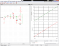
here is a DC sweep of input -

upload_2019-7-22_7-53-42.png

There is a slight offset at LM324 output because it cannot go all the way to ground,
20 mV I believe.


Regards, Dana.
 

Thread Starter

daba1955

Joined Apr 27, 2019
218
Heads up on the OP, originally I wanted a 0 - 10V DC, not PWM. that's because I believed that to be the standard for a motor controller speed control potentiometer. How wrong was I ?!

The motor speed control pot actually only has about 2V DC across it, so replicating the wiper DC voltage with a 0-5V pk-pk PWM signal should be a doddle. Strange controller though, at minimum speed the wiper voltage is 2V, reducing to 0V at maximum speed. That's not a deal-breaker, easily "invert" the control characteristics in code.

So, answering all the relevant posts.....

Convert to 0-10V DC PWM signal?
It wouldn't be a DC signal if it was PWM - I said in the first line of the OP
This might be simple, but I have a PWM signal from an arduino (5V pk to pk) that I want to convert to a 0-10V DC signal.
I believe the TS wants to convert the 0-5V PWM signal to its average duty-cycle value with a gain of two, giving a 0 to 10Vdc signal.
You believed correctly, crutschow, perhaps you misunderstood the first line of my post, that is exactly what I was originally looking to achieve.

you should use an OP AMP which has gain of two. for this application you need minimum 10 V of power supply (or you can use -+5V and a clamper circuit) and low noise materials.
I would not have had 10V available, this all has to work off a 5V dc supply.

Thanks everyone for your contributions, and the time you spent....
 

danadak

Joined Mar 10, 2018
4,057
To work off 5 V DC supply and generate a 10V DC signal when input is 5V DC
you need to generate a higher V to run the X 2 Opamp circuit in order to keep
a linear relationship between inpujt and output.

You could use a charge pump or boost converter to create the higher DC V needed.


Regards, Dana.
 

Thread Starter

daba1955

Joined Apr 27, 2019
218
To work off 5 V DC supply and generate a 10V DC signal when input is 5V DC
you need to generate a higher V to run the X 2 Opamp circuit in order to keep
a linear relationship between inpujt and output.

You could use a charge pump or boost converter to create the higher DC V needed.


Regards, Dana.
I think you missed the beginning of my previous post, I only need to generate 2V dc down to 0V dc from a 5V pk-pk PWN, so all i need is a charge pump, followed by a potential divider.

Since it is a motor speed controller, I don't think it will matter if the RC charge pump doesn't produce a straight-line level, the inertia in the motor will take care of any ripple...
 

Thread Starter

daba1955

Joined Apr 27, 2019
218
One other thought I am having is that since I will only need a bunch of preset speeds, I can use multiple digital outputs on an R-2R ladder network to give me as as many as I need ...

4 outputs = 16 speeds (including stopped)
5 outputs = 32 speeds
etc.
... followed by a 40% voltage divider (5V to 2V) should give me close to what I need
 

danadak

Joined Mar 10, 2018
4,057
I think you missed the beginning of my previous post, I only need to generate 2V dc down to 0V dc from a 5V pk-pk PWN, so all i need is a charge pump, followed by a potential divider.

Since it is a motor speed controller, I don't think it will matter if the RC charge pump doesn't produce a straight-line level, the inertia in the motor will take care of any ripple...
================================================================
This might be simple, but I have a PWM signal from an arduino (5V pk to pk) that I want to convert to a 0-10V DC signal.
I so do not understand from your original post.

The above says you have a 5V PWM signal, seems to imply you are going to change
its duty cycle to change V, and you later specified 0 - 5V DC which I took to mean the
PWM is filtered and running off 5V hence would vary 0 - 5 V DC at output of filter, and
you wanted that to create 0 - 10V DC.

0 - 5V DC in >> 0 - 10 V DC out

So I am thoroughly confused at this point.....


Regards, Dana.
 

Thread Starter

daba1955

Joined Apr 27, 2019
218
A very nice circuit, posted without any comments whatsoever ...

Please people, I don't need circuits designing any more, my required output voltage is LESS than I have available after smoothing the PWM signal, and I don't need a circuit with 12 or so components to drop it down.

It seems that some people, with good intentions, are not keeping up to date with following the thread, my situation has changed since I started the thread.
 

Thread Starter

daba1955

Joined Apr 27, 2019
218
================================================================


I so do not understand from your original post.

The above says you have a 5V PWM signal, seems to imply you are going to change
its duty cycle to change V, and you later specified 0 - 5V DC which I took to mean the
PWM is filtered and running off 5V hence would vary 0 - 5 V DC at output of filter, and
you wanted that to create 0 - 10V DC.

0 - 5V DC in >> 0 - 10 V DC out

So I am thoroughly confused at this point.....


Regards, Dana.
Please see the above post of mine - the situation has changed from the OP
 
Status
Not open for further replies.
Top