Facebook
 Google
 GitHub
 Linkedin

555 Timer Toy Piano
Hello everyone, I am an electronic engineering student studying at Staffordshire University and currently completing an industrial placement. I was given the most amazing opportunity ever at Christmas, the chance to visit the USA for 3 months during the summer and teach children, but not only that, I would be teaching them electronics! For two months I will be working at a Science and Engineering Camp in PA teaching children ages 8 – 17 electronics and touring for a month before returning to the UK to complete my final year of studies.
I have been told that the camp has projects available for the children and the children may also design their own if they wish. I was also asked to bring an idea/project with me to camp that I could teach the children.
I set about looking for suitable projects. Having just purchased a series of Mini Engineers notebooks written by Forrest M. Mims I started to flick through the circuits listed, looking for one that may be suitable. I immediately stumbled upon a 555 timer circuit that made a toy organ. I studied the circuit and couldn't believe I had never seen or thought of such an ingenious circuit before! It consisted of a 555 timer and various selectable values of C1 that were wired in parallel.
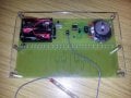
Toy Piano as viewed from the top.
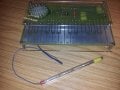
Toy Piano as viewed from the base.
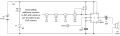
Schematic
Looking at the design I thought surely instead of selecting a different capacitance you could select a different resistance by changing say R2? Resistors are available in a much wider selection of values and they are cheaper… it’s a win win situation! I initially thought of just chaining lots of 1K resistors together and using a stylus to select which one I wanted, the further along in the chain, the higher the resistance and hence the lower the frequency. Then it occurred to me… surely I could re-produce the different frequencies of actual notes? I found a table on the internet with the different frequencies of notes on a piano, having extracted the values I wanted (Middle C (C4) to (C6)), I set about calculating appropriate resistor values. Using Excel I was able to calculate the different values that were needed and making use of the “goal seek” feature I could home in on an exact frequency by changing a resistor value. Once I had all of the resistor values I needed I decided a pre-set resistor could be used for the first note and then E12 values could be used for the other notes. I worked out which values I needed and then worked out the actual output frequency assuming 0% tolerance on the resistors. This allowed me to calculate the difference between the real frequency and the actual frequency. I was surprised to find out that the maximum deviation was only 0.915%
Armed with a circuit that I had drawn up using Circuit Wizard I breadboard the circuit to test it. Sure enough when a different resistor was selected on the breadboard using the piece of wire to simulate a stylus I got a different note! Despite some of the notes being off frequency a little I was pleasantly surprised at the quality of the notes produced. I did consider adding a variable resistor for each note to allow tuning of every note, but I decided this really wasn't necessary and I wanted to keep it nice and simple for the children I would be teaching it to. Any component that wasn't necessary was removed!
It was time to design the PCB. Taking inspiration from the Stylophone I came up with a PCB pattern using Circuit Wizard and set about manufacturing the PCB. I was using the toner transfer method for the very first time (having been used to the photo-resist method previously), so this was all very new to me. I printed the artwork onto a piece of acetate and placing a piece of baking paper on top of the acetate I started to iron it to the copper side of the PCB. I hadn't seen this method of using acetate directly onto a PCB used before so I was keen to try it. Once cool the artwork was peeled off leaving the toner transfer on the board. It was a little patchy in places so I grabbed an indelible pen and filled in some of the areas that needed it. The board now fully prepared was ready for etching. Placing the board into warm ferric chloride solution and rocking the processing tray back and forth my very first toner transfer PCB was etching before my eyes. Once etched I removed the toner using nail polish remover and once clean gave the board a good soaking in some tin plating solution to give the keys a nice durable finish. I drilled the board using a miniature hobby drill and stand and the board was complete.
This was the first time that I had used tin plating and I couldn't believe how easily the components soldered in place! I gave the board a quick functional test and was delighted to see that it worked first time.
I decided to showcase the circuit in all its glory by designing a really simple two piece clear Perspex case, which was cut using a laser cutter. The board was held in-between the two pieces using brass hexagonal supports and screws and the toy piano was complete… well nearly. I still needed a stylus! Scratching my head trying to think of something to make a stylus with, it suddenly dawned on me. I took an old pen and removed the ink, feeding a piece of cable screening down the tube I was able to splay it out on the end and heat shrink it in place. I soldered a little piece of wire to the end and viola, one simple stylus!
I then set about making a handbook for my new toy, explaining the design phases and how the children could build one too. I will be using this whilst teaching them how to build it in the summer. I have attached a copy if you are interested? Also included is also a page which details all of the parts which can be sourced from Rapid. Rapid Electronics deliver worldwide and they offer very competitive prices. I have included the parts list on the next post because it wouldn't fit in this one.
I have also attached copies of the schematic, a ZIP of the DXF files for the Perspex and the artwork and normal layout view in ZIP of the PCB. Please note, if printing the artwork for the PCB, ensure you select "No Scaling" on the print options. I advise printing out on paper first and testing by pushing the components through the paper. Things like DIL IC holders etc. will show you if the output is scaled or not.
Please do feel free to comment and make suggestions. I will of course keep you updated and let you know how the summer camp goes. Really excited and can't wait to go! I love teaching children and I love electronics, so I couldn't ask for a better summer!

Attachments
-
73.1 KB Views: 207
-
2.3 KB Views: 68
-
91.4 KB Views: 85
-
 45.4 KB Views: 779
 -
 44.5 KB Views: 822
 -
848.4 KB Views: 162