 Facebook
 Google
 GitHub
 Linkedin
INTRODUCTION:
A TDR (Time Domain Reflectometer) is an essential piece of equipment when working with cables and communications. However, commercial TDRs are very expensive, remaining in use with only large companies. This project aims to provide a cheap, functioning TDR for those interested in its basic operation and theory.
THEORY & MECHANICS:
This TDR works on a very simple principle, that waves are reflected from a fault along the cable. TDRs not only are able to discover the type of fault, but also the distance the fault is – useful in real life when digging up a mile of telephone cable would be impractical.
Put simply, this TDR works by emitting a pulse which is split at a BNC junction. Part of the signal goes straight to the oscilloscope, whilst the other travels down the cable. If there is a fault, then the pulse will be reflected back to the oscilloscope where it can be analyzed.
SCHEMATIC & COMPONENTS:
 [1]
[1]
2 10nF Capacitors
1 22nF Capacitor
1 4n7 Capacitor
1 1nF Capacitor
1 220pF Capacitor
1 47pF Capacitor
1 220μF Elec. Capacitor
1 78L06 6V Regulator
1 1N4148 Diode
1 74AC14 Schmitt Inverter
1 15K Resistor
1 150R Resistor
5 220R Resistor
1 22R Resistor
1 47R Resistor
1 BNC Connector
1 5 pole, 2 way switch
3 Jumpers
PCB:
 [2]
[2]
CONSTRUCTION:
Construction was very simple. A big thank you to Nerdegutta for making the PCBs.

OPERATION:
This is also simple. Connect the TDR to the BNC Junction. Then connect one end to the oscilloscope and one end to the cable under test. If there is no break, then you should have a clean, square pulse.
If not, then a pulse will be reflected, and the shape will reveal the type of fault.
Please note that the cable must be less than half of the wavelength that corresponds to the main frequency of the pulsetrain. Otherwise the reflected pulse will become mixed with the output pulse. This can be calculated with the simple formula:
λ=c/v
REFLECTIONS:
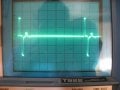
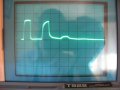
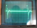
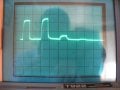
Below are some reflections, which can be used to determine the type of fault.
NO FAULT:

OPEN:

SHORTED:

RESISTANCE:

INDUCTANCE:

As can be seen, each has its own very distinct reflection.
I hope this has been useful.
Sparky
CREDITS:
[1], [2] Nerdegutta
EAGLE Files Nerdegutta
FURTHER READING:
http://www.epanorama.net/circuits/tdr.html
http://www.elektor.com/magazines/2011/october/time-domain-reflectometry.1948603.lynkx
A TDR (Time Domain Reflectometer) is an essential piece of equipment when working with cables and communications. However, commercial TDRs are very expensive, remaining in use with only large companies. This project aims to provide a cheap, functioning TDR for those interested in its basic operation and theory.
THEORY & MECHANICS:
This TDR works on a very simple principle, that waves are reflected from a fault along the cable. TDRs not only are able to discover the type of fault, but also the distance the fault is – useful in real life when digging up a mile of telephone cable would be impractical.
Put simply, this TDR works by emitting a pulse which is split at a BNC junction. Part of the signal goes straight to the oscilloscope, whilst the other travels down the cable. If there is a fault, then the pulse will be reflected back to the oscilloscope where it can be analyzed.
SCHEMATIC & COMPONENTS:
[1]2 10nF Capacitors
1 22nF Capacitor
1 4n7 Capacitor
1 1nF Capacitor
1 220pF Capacitor
1 47pF Capacitor
1 220μF Elec. Capacitor
1 78L06 6V Regulator
1 1N4148 Diode
1 74AC14 Schmitt Inverter
1 15K Resistor
1 150R Resistor
5 220R Resistor
1 22R Resistor
1 47R Resistor
1 BNC Connector
1 5 pole, 2 way switch
3 Jumpers
PCB:
[2]CONSTRUCTION:
Construction was very simple. A big thank you to Nerdegutta for making the PCBs.
OPERATION:
This is also simple. Connect the TDR to the BNC Junction. Then connect one end to the oscilloscope and one end to the cable under test. If there is no break, then you should have a clean, square pulse.
If not, then a pulse will be reflected, and the shape will reveal the type of fault.
Please note that the cable must be less than half of the wavelength that corresponds to the main frequency of the pulsetrain. Otherwise the reflected pulse will become mixed with the output pulse. This can be calculated with the simple formula:
λ=c/v
REFLECTIONS:
Below are some reflections, which can be used to determine the type of fault.
NO FAULT:
OPEN:
SHORTED:
RESISTANCE:
INDUCTANCE:
As can be seen, each has its own very distinct reflection.
I hope this has been useful.
Sparky
CREDITS:
[1], [2] Nerdegutta
EAGLE Files Nerdegutta
FURTHER READING:
http://www.epanorama.net/circuits/tdr.html
http://www.elektor.com/magazines/2011/october/time-domain-reflectometry.1948603.lynkx
Attachments
-
243.4 KB Views: 115
-
18.6 KB Views: 65
-
 137.2 KB Views: 830

")


