2 led timed circuit

Thread Starter

brozizds

Joined Aug 15, 2010
135
First I would like to Thank Bill Marsden for his tremendous help on this project, that I originally posted on 8/15/10. I built this beautifully designed circuit as the schematic showed (or so I thought :confused:) but I made a few mistakes, ok a lot :) and corrected most, but now at the end of the timed cycle the piezo buzzer doesn't go off when the red LED does and the stop switch has no effect at all, even at the end of the cycle. I only have 1.3 V at the collector on the PNP transistor. when I hit the start it will reset and the green LED lights and runs it's course. I'm not using an SCR but would like to but it's not on my schematic (Remember lack of knowledge) but I am going to use a internal variable resistor but not on my prototype. I know Bill is very busy on other projects and I would appreciate any help that you folks could give me!I have built a simpler timer from (the electronics club) but it is very inaccurate, but Bills schematic and in operation was very accurate when testing the LED's time. HELP!
 

Thread Starter

brozizds

Joined Aug 15, 2010
135
Bill, I tried to post the schematic in this reply but it won't fit here! It is yours from 8/18/10 . Thanks Jim
 

Wendy

Joined Mar 24, 2008
23,801
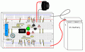
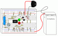
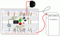
OK, I have two layouts, the Figure 1 will be my experimental version, the Figure 2 approaches what I think you are trying to do. I left extra room for big capacitors.


.........................................Figure 1


.........................................Figure 2


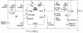
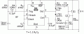
Then there is the schematic, which has been updated to reflect the values you need.


I'll let you know how it goes.

.
 

Attachments

Last edited:

Thread Starter

brozizds

Joined Aug 15, 2010
135
Thanks Bill, I will try the layouts tdy . Also I am assuming that Q1 is still NPN and Q2 is PNP am I correct? Also what is the value of Rt in fig. 2 (variable resistor).the trans. I got at RS the pin layout is diff. than the layout so I will follow EBC in yours. P.S. I'am asking this because of no parts list lol and lack of experience Thanks Jim
 

Wendy

Joined Mar 24, 2008
23,801
Nope, Q1 is PNP as shown on the schematic and Q2 is the NPN. I didn't modify the schematic that much, so maybe we found why it didn't work? :D

Are the drawings legible enough? I made the sonalert illustration for this project. That's how it works, if I make a component I have it forever on my PaintCAD.
 

Thread Starter

brozizds

Joined Aug 15, 2010
135
bill, on this post it does show Q1 as a 2N222A NPN http://forum.allaboutcircuits.com/showpost.php?p=269134&postcount=10
and Q2 as 2N2907A I took from the parts list boy am I confused lol thanks Jim but still tryin. I replaced Rt from 27K down to 10K for test porpose to shorten tests and didnt have a 240 ohm for R2 but used a 270 ohm I made Q1 the PNP and Q2 the NPN and when I apply 9V to my proto board the green LED lights up but time cycle doesn't run! the green LED Just stays on. Boy I wish we lived closer lol
 

Wendy

Joined Mar 24, 2008
23,801
Opps. My bad, the schematic has the right of it though. If I release this for publication it'll be fixed. I may go do it later tonight, but it has been an incredibly long day.
 

Wendy

Joined Mar 24, 2008
23,801
Good news and bad news. I just build it, didn't work for me either. I'll get back with you when I have it figured out, probably within a couple of hours.
 

Wendy

Joined Mar 24, 2008
23,801


OK, I had to reconfigure the SCR circuit a little, turns out the tap point was critical, and I increased the resistance to the primary gate of the SCR. It works. I also increased the loading, the piezo speaker was just too light a load for the alarm.

You probably noticed I changed the caps from Radio Shacks stuff. The 0.1µF Radio Shack offers were just too big and clunky for my tastes.

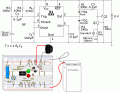
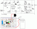
I combined the images, if you use Windows Picture and Fax Viewer it does a decent job of printing the above image out. Makes for easy construction.

Parts List

U1 - 555 IC
Q1 - PNP 2N2907A
Q2 - NPN 2N2222A
D1 - Red LED
D2 - Green LED
R1 - 330Ω ¼W
R2 - 240Ω ¼W
R3,4,6 - 10KΩ ¼W
R5 - 1KΩ ¼W
Rt - User Selected
C1,2,3 - 0.1µF
Ct - User Selected
S1,2 - Momentary Open Switch
Sonalert
9V Battery

While S1 is shown as normally closed, it doesn't matter either way.

I was tired that day about the NPN transistor, but it was right the first time I think.
 

Attachments

Last edited:

Wendy

Joined Mar 24, 2008
23,801
I've discussed it with several folks. While not my original goal, I'm going to turn this into one of my 555 articles. It is a pretty good demo of an SCR, and how the internal arrangement works. Thanks for the boost.
 

Dcrunkilton

Joined Jul 31, 2004
422
I've discussed it with several folks. While not my original goal, I'm going to turn this into one of my 555 articles. It is a pretty good demo of an SCR, and how the internal arrangement works. Thanks for the boost.
It looks like a good project to me. It has been thoroughly tested. You have the drawings. So, most of the work is done.
 

Thread Starter

brozizds

Joined Aug 15, 2010
135
Bill, I completed the protoboard as per schematic and applied 9V the red LED and Piezo buzzer went on when I hit the S1 the Green LED lit and timer ran its course then the red LED and Piezo went off Great ! Now for the questions lol. When I hit the stop S2 the piezo stops but red LED stays on . Did this happen with your proto and if so why? I was Hopping to have it go off with piezo. Also I noticed the Ct and Rt is user selected I'm thinkin to adjust the time , Correct? the higher ohm and higher uF the longer the time. OMG Bill the accuracy of time duration every time was perfect and now just the one thing that darn "RED LED" but now after workin with you on this project I'm beginning to see why you have that Quote but the author might be YOU ! LOL thanks for all your help and the added knowledge you have given me. JIM
I do have another project in mind to tie into this one (a digital countdown timer) lol
Ill probably start a new thread when I'm Ready . Get bact to me Please when you can! Thank you again and I use your quote alot at work!
 

Wendy

Joined Mar 24, 2008
23,801
The red light is the default condition. A 555 is binary, a 1 or a 0, 1 is green, 0 is red. If you turn the red light off this is a three state condition.

You could move the red LED in series with the SCR and R6, drop R6 to 330Ω to increase the LEDs brightness. I can show you on the schematic, but I'm hoping I'm done drawing the protoboard. R1 would stay however, it is used for more than the LED.

*****

Dang, just discovered a problem with my schematic. Guess I will redraw it a bit.
 

Attachments

Last edited:

Thread Starter

brozizds

Joined Aug 15, 2010
135
Bill, I did as you said to place the red LED in series with the SCR circuit and R6 , lowered the value to 330 ohm and it works exactly as I needed:DThanks so much for your help and understanding. I have changed the Ct to the 1000μF and raised the Ω value of Rt to reach the times I need and it works perfectly. Thanks Again :) Jim P.S. I am probably going to increase the size of the internal variable resistor for the longer times and the problem with the schematic wasn't a problem on your protoboard sketch . Correct? Thanks again its been fun:)
 

Wendy

Joined Mar 24, 2008
23,801
No problem, and glad to help. I'll be redrawing it a little and testing out your variation. I think I'll incorporate it in the article.
 
Top