
Hi everyone, this is a pretty simple project but i am a new to relays so..
Diagram here

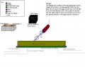
Goal:
Reversing polarities on a motor
(think of a electric car window )
Situation
I am buying racing seats for my car and i am planing to keep the electric slider that my original seats had, by re attaching it to the new racing seats. so i have a motor that connects to the track and i need it to go
forward (when a push button is pressed )
stop (when the push button is released )
backward (when another push button is pressed )
Click Here for A Diagram
or copy http://i20.photobucket.com/albums/b205/djkasra/MySeatSetup.jpg
Material
(2) Push Buttons
(1) Motor= 12V DC
(~10) Relay= 12V 30/40A opposite
Also
I am trying to make this a Memory seat, so
see diagram for this section
cause1:
putting the key in the ignition
Reaction1:
the seat would move forward untill the Forward Triger hits the Forward Stoper.
cause2:
Taking the Key out of ignition
Reaction2:
the seat would move Backward untill the Back Triger hits the Backward Stoper.
Helpful Knows
when Key is in ignition a wire that is known has 12v (other times 0v)
When Key is out of ignition that same wire has 0v
Help With:
i am not sure how i can connect the relay(s) so that when i press
Diagram here
Goal:
Reversing polarities on a motor
(think of a electric car window )
Situation
I am buying racing seats for my car and i am planing to keep the electric slider that my original seats had, by re attaching it to the new racing seats. so i have a motor that connects to the track and i need it to go
forward (when a push button is pressed )
stop (when the push button is released )
backward (when another push button is pressed )
Click Here for A Diagram
or copy http://i20.photobucket.com/albums/b205/djkasra/MySeatSetup.jpg
Material
(2) Push Buttons
(1) Motor= 12V DC
(~10) Relay= 12V 30/40A opposite
Also
I am trying to make this a Memory seat, so
see diagram for this section
cause1:
putting the key in the ignition
Reaction1:
the seat would move forward untill the Forward Triger hits the Forward Stoper.
cause2:
Taking the Key out of ignition
Reaction2:
the seat would move Backward untill the Back Triger hits the Backward Stoper.
Helpful Knows
when Key is in ignition a wire that is known has 12v (other times 0v)
When Key is out of ignition that same wire has 0v
Help With:
i am not sure how i can connect the relay(s) so that when i press
- Push button one the motor would spin clockwise
- Push button two the motor would spin counterclockwis
- How to use the setup that i have with tigers and stoppers to obtain the memory seat.
Attachments
-
 41.5 KB Views: 56


