![]() |
|
|||||||
| The Projects Forum Working on an electronics project and would like some suggestions, help or critiques? If you would like to comment or assist others with their projects, this is the place to do it. |
|
|
|
Thread Tools | Display Modes |
|
#1
|
|||
|
|||
|
I am trying to put together a circuit to take a signal from a fingerprint reader and turn it into a signal to open a latch.
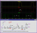
Long story short, I have located pads on the fingerprint reader that are high (~3-3.5v) when the proper fingerprint is swiped and low (0v) when no finger or the wrong finger is swiped. Here is my problem. To activate the reader a button is depressed. For a split second the area that I would like to use goes high then immediately goes back to low. To remedy this I need to make a circuit that will only accept a high signal that lasts more than 1 or 2 seconds. It will disregard any high signal that lasts less than one second. Then this circuit can ultimately trigger my relay or latch to open the door. I know this probably sounds simple, but I am a beginner. To give you an idea, I have been poking around on this circuit board for days (literally) with a multimeter looking for a suitable set of contacts. I understand basic resistors, capacitors, transistors and that sort of thing. Please ask any questions needed for clarity. Also, when responding talk like you would to a 2nd grader. :-) |
|
#2
|
||||
|
||||
|
How big are you? "SO BIG" aww now eat your peas.
(that may be younger than 2nd grade) The easiest way I can think of would be a microcontroller. It could be a simple few lines of code. Start a timer when an input pin goes high. Stop when it goes low. If the elapsed time is >1.5 seconds then output a high on an output pin else reset and wait for the next high.
__________________
-rm- |
|
#3
|
|||
|
|||
|
I am familiar with that concept but have not the slightest idea how to put it into practice. What is the best microcontroller for this project and how do you program it? Part numbers and sources would be really helpful!
|
|
#4
|
||||
|
||||
|
Get yourself an Arduino.
Very easy to learn and implement. You can have the whole project ready in a few hours after opening the box. You dont need a separate programmer, just the arduino and a usb cable. (It comes with it) http://www.sparkfun.com/commerce/pro...roducts_id=666 $30 and your good.
__________________
-rm- |
|
#5
|
|||
|
|||
|
And programming this thing is easy?
I plan posting a writeup when this thing is completed. I can't wait to get flamed for using such a powerful tool for such a dumb simple task. |
|
#6
|
||||
|
||||
|
This thing is super easy to program. It has its own 'C' language and about 10 million tutorials on line to get you going.
But for your project, you will use around 5 lines of code. really. Another thing. After you are done with the programming, you can remove the chip and put it in your circuit, then spend $5 and get a replacement micro. Or, to make connections easier, use the whole thing as-is in your design.
__________________
-rm- |
|
#7
|
|||
|
|||
|
Sounds like a no brainer.
Last thing...do you think the arduino would be happy running off the 4-6 volt supply provided by the onboard battery of the reader? Is it stable when removed from power or does it erase the program? I may end of having to hook it to a spot on the board that is only powered on when the reader is on. Hmm... Every time I think I have this project figured out another question comes up. |
|
#8
|
||||
|
||||
|
It runs off 5v and has an onboard regulator. You will be fine.
you can power it off your existing circuit. It uses flash memory which holds its memory through power off and power removal. It is idiot proof.
__________________
-rm- |
|
#9
|
||||
|
||||
|
Not until you have seen how easy this can be done.
You just need a CD40106B CMOS IC and three other components. If you change the value of resistor, the time before triggering can be adjusted. As there are five more inverter gate left over, you can use them to buffer the input signal(recommended, using two inverters in series) and change the polarity of the output trigger to positive going edge.
__________________
L.Chung |
|
#10
|
||||
|
||||
|
Awww, but whats the fun in that?
AND that would only cost like $1. WAIT, wait, wait.. I think I miss read your first post. You want to take the very fast pulse and PRODUCE a 1 to 2 second high? or ignore any any pulses shorter than 1.5 seconds? Regardless, after the circuit is triggered, how long do you want the high signal? or how long do you need the resulting high to remain high? The way Im seeing it is, you want the people to have to hold th button for at least 1.5 seconds, then send a pulse.
__________________
-rm- |
|
| Tags |
| activate, circuit, high, seconds |
Similar Threads
|
||||
| Thread | Thread Starter | Forum | Replies | Last Post |
| Total Resistence in Parallel circuit | AWSariti | General Electronics Chat | 14 | 02-27-2009 11:44 AM |
| Electronic Circuit Design Help Needed. | R.Stephen | The Projects Forum | 4 | 12-05-2006 08:01 AM |
| Circuit designers help needed | R.Stephen | The Projects Forum | 1 | 03-03-2006 09:00 PM |
| the term "common" | shelly50 | General Electronics Chat | 27 | 01-23-2006 04:02 AM |
| RC high pass circuit | sridhar10chitta | General Electronics Chat | 1 | 12-24-2005 09:36 AM |
| Thread Tools | |
| Display Modes | |
|
|