 Facebook
 Google
 GitHub
 Linkedin
Hi All,
My first posting and it's a doozy.
My skill level is basic. I actually had some EE courses but that was back when dinosaurs ruled the earth and you did your calculations with slide rules.
I came up with a schematic for this project but I have my doubts about it.
I'm building a sofa-bed for a RV. The bed uses two electric actuators to go from the bed to the sofa position and back again. Since this is an electronics forum let's just assume the mechanics are what they are and can't be changed. That's a whole other discussion.
I'm using actuators from Firgelli Automation. I'd provide a link but I don't want anyone thinking this is a stealth ad. I tried to get this to work from just one actuator but failed so I went to two. That can also be a whole other discussion. These actuators use non-adjustable internal limit switches and have just two wires for input. You apply current and the actuator fully extends then stops on it's own. Reverse the current and it closes all the way then stops. One actuator extends 6" and the other 12". The 12" is already installed and the 6" is in the mail.
My images show up in the message editing window but not in the preview window. I've included a link for each.
Here is the sofa-bed under construction.
http://larry.wvnet.edu/~van/pics/100314-32-j.jpg
Here is the mount of the 12" actuator. The board is mounted vertically under the middle of the sofa. You're looking at the end that will be pointed at the back of the sofa-bed.
http://larry.wvnet.edu/~van/pics/100407-030-j.jpg
This is looking at the middle front of the sofa-bed. The "seat platform" rests on and is bolted to the angled metal you see here which is driven by the 12" actuator. The actuator is attached to the right side of this board which I'll refer to as the "drive board".
http://larry.wvnet.edu/~van/pics/100407-088-j.jpg
On the left side of the drive board is mounted this lifting arm. The 6" actuator will be attached to this when it arrives.
http://larry.wvnet.edu/~van/pics/100412-29-j.jpg
Here is a rough sketch of how things are laid out. Not all elements are shown and not to scale. The sofa-bed is in the bed position. In the view from the right end of the sofa-bed you can see that the 12" actuator is closed. It is attached to what I call the "seat platform". The seat platform is attached to the "back platform" via hinges where they meet.

http://larry.wvnet.edu/~van/pics/Start-0-right.jpg
Here is the view looking from the left end. The 6" actuator is attached to the "lifting arm".

http://larry.wvnet.edu/~van/pics/Start-0-left.jpg
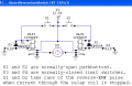
Here is the schematic I've come up with. It uses relays, limit switches and diodes. I have plenty of each and I'm comfortable working with with these. It might be nice to make this more solid state at some time but I've been working on this thing for almost two months now and I'd just like to get it finished.

http://larry.wvnet.edu/~van/pics/electrical_layout-500.jpg
In the schematic actuator "A" represent the 6" and "B" is the 12" one. The inputs on the left for each actuator are tied together at a DPDT (on) off (on) switch. I'll add the limit switches to the drawings as I walk through the steps I'm trying to accomplish.
Step 1. 12v Power is applied to both actuators. Positive power to the top most of each pair. Assume correct polarity at the actuators. Actuator "B" doesn't move since neither #3 or #4 limit switches are closed. Actuator "A" extends to 6" causing the lifting arm to pivot upward raising the "back platform" which is hinged to the "seat platform". During this pivot the lifting arm momentarily trips limit switch #2 but because of the diode in parallel with the switch it has no effect on Actuator "A". At actuator "A"'s full extension it closes limit switch #3 and stops.

http://larry.wvnet.edu/~van/pics/sofa_positions-1.jpg
Step 2. With limit switch #3 closed power now goes to actuator "B". This causes the seat platform to move to the left, in this view, which also causes the back platform to tilt further up. As the seat platform moves forward it first trips limit switch #4 which has no effect since it is already receiving power from via limit switch #3. After the seat platform has travelled far enough forward it trips limit switch #1

http://larry.wvnet.edu/~van/pics/sofa_positions-2.jpg
Step 3. This is the step where I have my doubts about my schematic. With limit switch #1 tripped it powers the two relays which reverse the polarity of the power going to actuator "A". This causes actuator "A" to start to close and lowers the lifting arm. It comes off of limit switch #3 but Actuator "B" continues to extend because of limit switch #4. Actuator "B" will stop when it's internal limit switch is tripped at full extension. Actuator "A" stops closing when it trips limit switch #2. This represents the sofa-bed in the sofa position. The back platform is supported by the "back rest" at the top and by the lifting arm at the bottom.

http://larry.wvnet.edu/~van/pics/sofa_positions-3.jpg
Here's my two doubts about this step. Is it safe to assume the two relays will activate simultaneously? If not you have a short. After the two relays trip will the path through both relay coils provide a path of least resistance so no power goes to actuator "A"?
Step 4. To go from the sofa position to the bed position isn't as big a deal since Actuator "A" doesn't have to change directions. Reverse power activates just Actuator "B" the seat platform travels far enough to the right to allow limit switch #1 to open. Then Actuator "A" goes to the closed position which lowers the lifting arm. Both actuators then stop at internal limits.
http://larry.wvnet.edu/~van/pics/sofa_positions-4.jpg
OK, for those of you who I haven't either bored or confused to death, Thanks for your time. I hope I was able to make sense of it all. If you have any questions just let me know. After two months this thing is giving me headaches.
Thanks again,
Dave
PS. In case you want to kill some time:
Actuator "B" in operation - 6MB avi file.
My FAIL of a lifter mechanism - 6Mb avi file
As a added attraction you can hear my Quality Control Engineer giving her opinion of the project at 34 secs.
PPS. In case you are REALLY BORED:
My build thread at RV.net.
My first posting and it's a doozy.
My skill level is basic. I actually had some EE courses but that was back when dinosaurs ruled the earth and you did your calculations with slide rules.
I came up with a schematic for this project but I have my doubts about it.
I'm building a sofa-bed for a RV. The bed uses two electric actuators to go from the bed to the sofa position and back again. Since this is an electronics forum let's just assume the mechanics are what they are and can't be changed. That's a whole other discussion.
I'm using actuators from Firgelli Automation. I'd provide a link but I don't want anyone thinking this is a stealth ad. I tried to get this to work from just one actuator but failed so I went to two. That can also be a whole other discussion. These actuators use non-adjustable internal limit switches and have just two wires for input. You apply current and the actuator fully extends then stops on it's own. Reverse the current and it closes all the way then stops. One actuator extends 6" and the other 12". The 12" is already installed and the 6" is in the mail.
My images show up in the message editing window but not in the preview window. I've included a link for each.
Here is the sofa-bed under construction.
http://larry.wvnet.edu/~van/pics/100314-32-j.jpg
Here is the mount of the 12" actuator. The board is mounted vertically under the middle of the sofa. You're looking at the end that will be pointed at the back of the sofa-bed.
http://larry.wvnet.edu/~van/pics/100407-030-j.jpg
This is looking at the middle front of the sofa-bed. The "seat platform" rests on and is bolted to the angled metal you see here which is driven by the 12" actuator. The actuator is attached to the right side of this board which I'll refer to as the "drive board".
http://larry.wvnet.edu/~van/pics/100407-088-j.jpg
On the left side of the drive board is mounted this lifting arm. The 6" actuator will be attached to this when it arrives.
http://larry.wvnet.edu/~van/pics/100412-29-j.jpg
Here is a rough sketch of how things are laid out. Not all elements are shown and not to scale. The sofa-bed is in the bed position. In the view from the right end of the sofa-bed you can see that the 12" actuator is closed. It is attached to what I call the "seat platform". The seat platform is attached to the "back platform" via hinges where they meet.
http://larry.wvnet.edu/~van/pics/Start-0-right.jpg
Here is the view looking from the left end. The 6" actuator is attached to the "lifting arm".
http://larry.wvnet.edu/~van/pics/Start-0-left.jpg
Here is the schematic I've come up with. It uses relays, limit switches and diodes. I have plenty of each and I'm comfortable working with with these. It might be nice to make this more solid state at some time but I've been working on this thing for almost two months now and I'd just like to get it finished.
http://larry.wvnet.edu/~van/pics/electrical_layout-500.jpg
In the schematic actuator "A" represent the 6" and "B" is the 12" one. The inputs on the left for each actuator are tied together at a DPDT (on) off (on) switch. I'll add the limit switches to the drawings as I walk through the steps I'm trying to accomplish.
Step 1. 12v Power is applied to both actuators. Positive power to the top most of each pair. Assume correct polarity at the actuators. Actuator "B" doesn't move since neither #3 or #4 limit switches are closed. Actuator "A" extends to 6" causing the lifting arm to pivot upward raising the "back platform" which is hinged to the "seat platform". During this pivot the lifting arm momentarily trips limit switch #2 but because of the diode in parallel with the switch it has no effect on Actuator "A". At actuator "A"'s full extension it closes limit switch #3 and stops.
http://larry.wvnet.edu/~van/pics/sofa_positions-1.jpg
Step 2. With limit switch #3 closed power now goes to actuator "B". This causes the seat platform to move to the left, in this view, which also causes the back platform to tilt further up. As the seat platform moves forward it first trips limit switch #4 which has no effect since it is already receiving power from via limit switch #3. After the seat platform has travelled far enough forward it trips limit switch #1
http://larry.wvnet.edu/~van/pics/sofa_positions-2.jpg
Step 3. This is the step where I have my doubts about my schematic. With limit switch #1 tripped it powers the two relays which reverse the polarity of the power going to actuator "A". This causes actuator "A" to start to close and lowers the lifting arm. It comes off of limit switch #3 but Actuator "B" continues to extend because of limit switch #4. Actuator "B" will stop when it's internal limit switch is tripped at full extension. Actuator "A" stops closing when it trips limit switch #2. This represents the sofa-bed in the sofa position. The back platform is supported by the "back rest" at the top and by the lifting arm at the bottom.
http://larry.wvnet.edu/~van/pics/sofa_positions-3.jpg
Here's my two doubts about this step. Is it safe to assume the two relays will activate simultaneously? If not you have a short. After the two relays trip will the path through both relay coils provide a path of least resistance so no power goes to actuator "A"?
Step 4. To go from the sofa position to the bed position isn't as big a deal since Actuator "A" doesn't have to change directions. Reverse power activates just Actuator "B" the seat platform travels far enough to the right to allow limit switch #1 to open. Then Actuator "A" goes to the closed position which lowers the lifting arm. Both actuators then stop at internal limits.
http://larry.wvnet.edu/~van/pics/sofa_positions-4.jpg
OK, for those of you who I haven't either bored or confused to death, Thanks for your time. I hope I was able to make sense of it all. If you have any questions just let me know. After two months this thing is giving me headaches.
Thanks again,
Dave
PS. In case you want to kill some time:
Actuator "B" in operation - 6MB avi file.
My FAIL of a lifter mechanism - 6Mb avi file
As a added attraction you can hear my Quality Control Engineer giving her opinion of the project at 34 secs.
PPS. In case you are REALLY BORED:
My build thread at RV.net.

")


