smooth DC output from full wave rectifier

Thread Starter

davidhills

Joined Sep 14, 2008
11
Morning

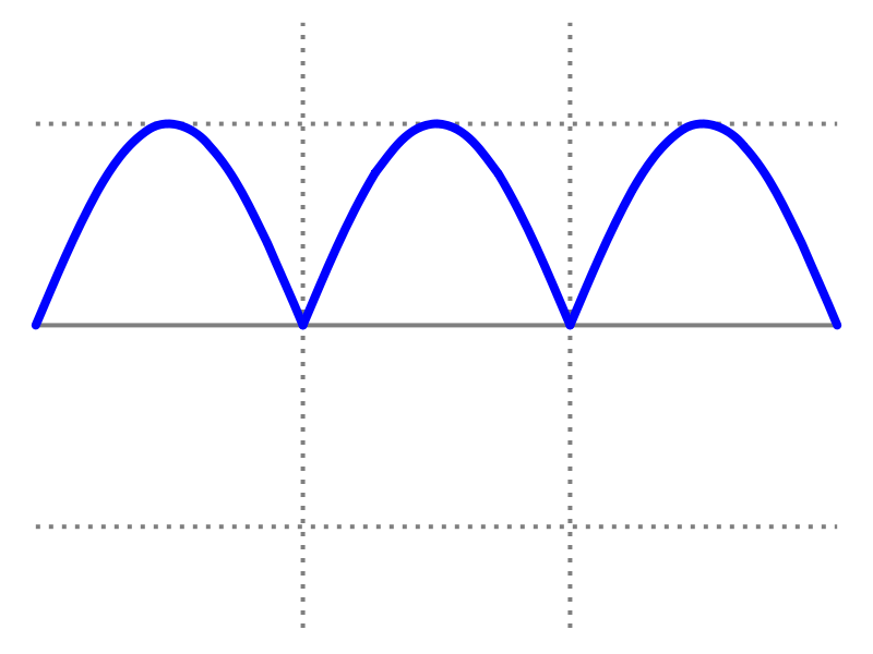
I have a full wave 28 volt rectified output from a 24volt battery charge.

I would like to tap off the output, 12volts dc to run a digitial amp meter, which will measures the chargers output current.

I think, because the output ripple is 100%, I can not use a 12 volt zenor configuration?( the digital amp meter draws I guess 200ma, it flaterned a pp3 9volt battery pretty quickly)

I can't smooth the 28 volts output, because I would need a massive capacitor to cope with the 100amp output capacity of the charger (fork lift truck 1600 amp hour). Also maybe for lead acid charging the 50hz ripple is good?

Whats the best way to tap off the 12 volts and smooth it?

thanks


David
 

bertus

Joined Apr 5, 2008
22,942
Hello,

You can "isolate" the ripple from the 24 Volt with a diode.
Then you can put a elco afther the diode.
See schematic.
The regulator must be cooled.

Greetings,
Bertus
 

Attachments

nanovate

Joined May 7, 2007
666
because the output ripple is 100%
Could you explain what you mean by this?

I will assume you mean that there is some ripple voltage on top of a 28V DC line to charge some 24V batteries. To go from 28V to 12V using a linear regulator like the LM7812 requires some "cooling" as Bertus mentioned.

If you do have massive amounts of ripple then you need to redesign the power supply.
 

bertus

Joined Apr 5, 2008
22,942
Hello,

That depends on the current the meter uses.
You can help the zener with a transistor as in the attached schematic.

Greetings,
Bertus
 

Attachments

bertus

Joined Apr 5, 2008
22,942
Hello,

Do you have a link to the specifications of the meter ?
In the picture it says 5 - 18 Volts.
Why don't you regulate the voltage to 15 Volts ?
This will reduce the heat a little bit.
Most current will be drawn if the backlite is on.

Greetings,
Bertus
 

Audioguru

Joined Dec 20, 2007
11,248
Your photo showed a low current LCD display. But you bought a high current LED display. It has at leat 26 segments at maybe 10mA each which is a current of 260mA. It might be 520mA or more.

Many of these meters cannot measure their own supply voltage. They need a separate power supply.
 

Thread Starter

davidhills

Joined Sep 14, 2008
11
Thanks for your relplys

with 14 segements on it draws 50ma so If I design for peak current of 300ma That should be good


If I've got 28volts peak full wave in and I want and isolated 10volt smooth
DC out put with 4.5watt (round it up to 10watt) load driving capability.

see poor attachment of circuit. I need help with specifiction for ELCO and Zenor resister

Thanks


Everyone
 

Attachments

SgtWookie

Joined Jul 17, 2007
22,230
See the attached schematic; click on it to open it in a new window. You may have to click on it a second time to see it clearly.

V1 and D1 represent the transformer and rectifier inside your battery charger.

D2 is a simple 1A rectifier diode. You could use a 1N4002 to 1N4007, or a 1N5402 to 1N5407. This diode permits current to flow in to charge up capacitor C1, but prevents current flow back out towards the battery or the charger. C1 must be at least 470uF in order to keep up with the 300mA current demand of your load.

The LM317 is an analog voltage regulator that's available just about everywhere. You set it's output voltage using just two resistors. A 120 Ohm resistor from the OUTPUT to the ADJ terminal and an 820 Ohm resistor from the ADJ terminal to ground (or in this case, the Batt- connector) will give a nominal 10v output. The 10uF capacitor helps the regulator with transient suppresion.

The LM317 will be dissipating roughly 4W of power by itself. You will need to use a heat sink on the regulator to dissipate that power. A dab of heat sink compound will make the contact between the back of the LM317 and the heat sink much more efficient.
 

Attachments

Top