ZANUSSI DRYER CONTROL BOARD REPAIR (model ZDC67550W)

Thread Starter

greenisland

Joined Jan 7, 2020
82
Hello all,

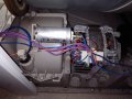
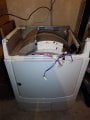
I have an electric clothes dryer that has decided it wants to dry no more. I am reluctant to send it to white good heaven as Zanussi would hope. I have began an thorough investigation into the matter employing all my limited resources, and believe me they are limited, creativity and knowledge and have come up completely stumped, I appeal to all who are knowledgeable in such matters to assist, throw me a line.
The beast shows no sign of life at all, dead she is, aye dead, no leds or beeps or even rapid eye movement, I have checked the obvious, plug fuse, power at socket, and temp. sensor, even checked to make sure the electricity was'nt cut off.

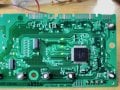
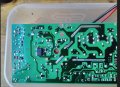
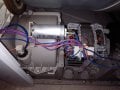
But seriously looking online several sites list powerboard issues a common problem for washers and dryers, specifically LNK chip failure.
If this IC fails/shorts there is a 3 watt resistor (mine 47ohm) which acts as a fuse and blows open.

I removed my board and this resistor was indeed open, I replaced the resistor with same,which just blew open when powered, typical; I then ordered a repair kit from fleabay which had a LNK304GN chip and a 3 watt 47ohm resistor.
I replaced the chip and resistor but the board still shows no sign of life.
With the board removed from the machine and connected to the mains some leds should light on the LNK chip side at power on.
I am using a isolating mains transformer as some form of safety.

The new 47ohm resistor is ok
I have removed and tested diodes marked with a circle, ok
Checked diode above the LNK chip ok
Caps marked with an X have no charge (low power 35v caps), high volt cap marked with a tick mark is charging 320v.
Also checked opto coupler and opened rotary switch and cleaned with alcohol.
Checked L, 3 in total, I think chokes?, interfernce suppression? they show conductivity.

The Link chip seems to be outputting nothing, there is 5.8v at the bp pin 350v at the drain and .5v at the fb pin, ov at source pins.
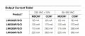
I have looked at the chip data sheet but this is beyond me, and causes severe pain in my brain, I cannot find a schematic online.

Are there other common components beside the LNK IC that fail on these boards?
Is there a way of testing the LNK chip?, is chip removal required for testing?

I only have a digital multimeter for testing and a very limited knowledge of electronics.

Any suggestions would be greatly appreciated.
 

Attachments

Last edited:

Dodgydave

Joined Jun 22, 2012
11,302
This is the nearest i can find to your pcb, the 3 unknown shorts are Inductors, what is U5 chip as i think its a switchmode type too.?

NOTE D4 &D5 are drawn the wrong way..
whirlpool_awe_series_ps_lnk304_ic_power_supply_sch.pdf_1.png
 
Last edited:

Thread Starter

greenisland

Joined Jan 7, 2020
82
Thanks for your help Dodgydave

U5 is a C393C Chip, which is listed as a comparator.

Schematic has a lot of similarities; mine has only one diode after R1 and one high voltage cap, cannot see L1 on mine between cap and transformer. The R2, C3 and D5 layout leading to transformer and drain of LNK is identical.
Is T1 receiving a pulsed signal at pin 4 by way of D1 and D2, only rectifying half of the ac signal and C1 and C2 constantly being charged and discharged?

Two inductors to the right of the rotary swich marked L1 and L2 are each 4700 in value (yellow,violet and red) so are these 4.7h in value? do they tend to blow open, I mean if they show any low resistance like mine did, are they working?

Just looking at your schematic is the LNK chip output 5v?, and is this for the logic supply?.
The 12v from T1 is for powering the relays?

Sorry for all the questions, but I'm confused as normal, can't seem to get my head around switch mode power supply, many people show repairs to these boards online, even upload Youtube video, but they don't go into any detail, they just say replace the chip and resistor.....ok done that and it's still dead.
 
Last edited:

Dodgydave

Joined Jun 22, 2012
11,302
Yes the Inductors are normally low resistance, 4700uH ( 4.7mH) , the transformer gets pulsed from pin 4 , and the output is regulated by the zener or optocoupler on pin 2 (fb).
The transformer output gives out 12V for the relay and possibly 5V for the microcontroller.
 

Thread Starter

greenisland

Joined Jan 7, 2020
82
Yes the Inductors are normally low resistance, 4700uH ( 4.7mH) , the transformer gets pulsed from pin 4 , and the output is regulated by the zener or optocoupler on pin 2 (fb).
The transformer output gives out 12V for the relay and possibly 5V for the microcontroller.
Ok I'm listening and learning, interesting, optocoupler linked to feedback on LNK IC.

Am I correct in saying then, the LNK chip varies the frequency /voltage? or both? to transformer pin 1? and if so this is based on the feedback from the optocoupler? (acting similar to an op-amp)
At the same time there is a constant fixed pulse being supplied to pin 4.

And the inductors; they are filtering out noise produced by this switching action?

Sorry about all the village idiot questions, but where on the board can i test only armed with a multimeter?
 
Last edited:

Dodgydave

Joined Jun 22, 2012
11,302
Yes, the LNK chip varies the pulse width to lower or increase the output which is set by the fb pin, or if using an optocoupler there's usually a zener diode in series with the opto led .
 

Thread Starter

greenisland

Joined Jan 7, 2020
82
Ok Dave, I changed the electrolytic caps, still no power. I've been reading a bit about switchmode, still confused.

Can you please help clarify: (refering to your schematic)
1 Pins 1 and 4 are on the primary side of the transformer?
2 Pin 4 on LNK is Drain (+320v dc power supply to LNK)?
3 Pins 5,6,7,8 on LNK are souce pins from the internal mosfet (ouput of LNK +)?

4 The pulsed output of the LNK (which varies depending on load/feedback) is not fed into the primary of the transformer, but the secondary winding?, surely the LNK output needs to feed the primary?
 

Dodgydave

Joined Jun 22, 2012
11,302
Yes the LNK chip pulses the Primary side ( in the example drawing the transformer primary are pins 1,4), you need to try and re draw your pcb to see how its entirely different, dual sided PCBs are a pain to re engineer.

Note the example drawing has the wrong pin numbers on it , pins 1,2, 7,8 are all connected together as the S pin.

LNK304-pin-configuration-typical-application.png
 
Last edited:

Thread Starter

greenisland

Joined Jan 7, 2020
82
Yes the LNK chip pulses the Primary side ( in the example drawing the transformer primary are pins 1,4), you need to try and re draw your pcb to see how its entirely different, dual sided PCBs are a pain to re engineer.

Note the example drawing has the wrong pin numbers on it , pins 1,2, 7,8 are all connected together as the S pin.

View attachment 270863
Your last reply with the pinout and schematic is from the datasheet, I've looked at that before and copied both on paper (using it as a legend).
Putting the first schematic pinout error aside, the datasheet makes more sense to me, the output souce pin on the data sheet schematic is feeding the coil/transformer.

The first schematic originator looks Polish. Electrolux seem to make a lot of domestic appliances trading under different names.

Is the first schematic source connection to ground wrong? (forget the pin no. error)

You're right, no way around it I will attempt to draw my board as a schematic, to the primary at least, hard to see though where a connection is made from one side to the other.
 

Thread Starter

greenisland

Joined Jan 7, 2020
82
So thats the output of the LNK (source) going to the secondary????, not primary
Replying to my own post now, Ha Ha

Upon consideration I think I'm beginning to see the error of my reasoning, I am thinking of the output of Source in a DC sense, not pulsed artificial AC signal, the pulsed output to secondary side of transformer will pass through some of the caps to the 5v rail.
 

twohats

Joined Oct 28, 2015
447
Have you got power coming to R1, ( Dodgydaves circuit)? Are there any hidden fuses?
When those I.C's fail, maybe the motor has a leak to ground/earth.
Could you substitute a large incandescent bulb in place of the motor or in series with it.
I've been lucky, repaired two machines with the eBay kits.
Good luck.............
 

Thread Starter

greenisland

Joined Jan 7, 2020
82
Big thanks for all your help Dodgydave and twohats,

I got the board back to life, she lives!

I had been attempting repairs on this board for many days before posting here, and trying peoples patience, I have thought a few times that even if it is the board, what made it fail, and will it fail again, if I do get the board to work?. I did contact the ebay seller a week ago, after the first chip replacement failure, and he recommended a chip in the same family but could handle more power.
The original chip was IC LNK304GN, he recommended a LNK305GN, he seems to sell a hell of a lot of these kits.
Second chip arrived today (LNK305GN) and board chirps, and green leds light, success.
If this happens again I will put in a IC socket.

I have googled your post twohats about about a possible earth leak, and testing using a meter set on Mohms. I will test before powering up. I did read somewhere a lot of washing machines have this issue seemingly, they keep tripping the RCB in the mains board.

This is making me think....this dryer was stored in a 20ft steel shipping container for the last three years, we bought it new about four years ago, used it moderately, then moved house, we......ok I got into the habit of using a self service launderette close by, dryer was only recently brought into new home; she who must be obeyed was becoming increasingly vocal about it, anyway it worked once then died.
I was surprised when I took off the side panel and seen the crust on the motor housing, only time I ever seen this before was viewing a used car where owner lived close by the sea.

I think I will proceed as you suggest twohats, with caution!, and substitute a mains bulb for the motor first and maybe check earth issue, clean around brushes, connections with IPA and look at motor cap.
 

Attachments

Last edited:

Thread Starter

greenisland

Joined Jan 7, 2020
82
Big thanks for all your help Dodgydave and twohats,

I got the board back to life, she lives!

I had been attempting repairs on this board for many days before posting here, and trying peoples patience, I have thought a few times that even if it is the board, what made it fail, and will it fail again, if I do get the board to work?. I did contact the ebay seller a week ago, after the first chip replacement failure, and he recommended a chip in the same family but could handle more power.
The original chip was IC LNK304GN, he recommended a LNK305GN, he seems to sell a hell of a lot of these kits.
Second chip arrived today (LNK305GN) and board chirps, and green leds light, success.
If this happens again I will put in a IC socket.

I have googled your post twohats about about a possible earth leak, and testing using a meter set on Mohms. I will test before powering up. I did read somewhere a lot of washing machines have this issue seemingly, they keep tripping the RCB in the mains board.

This is making me think....this dryer was stored in a 20ft steel shipping container for the last three years, we bought it new about four years ago, used it moderately, then moved house, we......ok I got into the habit of using a self service launderette close by, dryer was only recently brought into new home; she who must be obeyed was becoming increasingly vocal about it, anyway it worked once then died.
I was surprised when I took off the side panel and seen the crust on the motor housing, only time I ever seen this before was viewing a used car where owner lived close by the sea.

I think I will proceed as you suggest twohats, with caution!, and substitute a mains bulb for the motor first and maybe check earth issue, clean around brushes, connections with IPA and look at motor cap.
Just a quick note, machine working fine, very happy with the result, I think there must have been some degree of condensation on this board after being stored for all that time in the shipping container. I have a mig welder and power tools still in the container, when I need them I will make sure to blow a heater into them before applying power.

I found an old boy based in Gran Canaries who repairs electronics on Youtube, his videos are the best I've seen so far; clear english and schematics drawn by hand, all explained plainly in a laid back manner.

ATX powersupply repair guide:
 
Last edited:
Top