Would like to design a pulse on shot that is triggered from a rising edge

Thread Starter

mike _Jacobs

Joined Jun 9, 2021
223
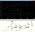
You can use this simple circuit:
View attachment 302375
ADDED:

Because simple RC circuit does not generate good shaped pulse
exactly in time, defined by R4 and C1 values, but this circuit does.
Also, as you said, circuit "needed fast slew on the output".

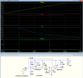
Feel free to modify circuit for your needs, for example -
decrease capacitance of C1:

View attachment 302386
would you mind telling me a bit more how it works? I’m interested in it for sure
 

Thread Starter

mike _Jacobs

Joined Jun 9, 2021
223
Back to the topic at hand.

Is it possible to create a comparator based monostable multi vibrator without a negative voltage supply?
After seeing the principal of operation, i doubt it?
 

Thread Starter

mike _Jacobs

Joined Jun 9, 2021
223
So what is the rise time of this trigger, at what voltage in the trigger due you want an output, and how long an output pulse do you want?
Hi there

The rise time was very slow, around 200ms
However i am trying to consider using something other then my original circuit to trigger it.

I just built a monostable multivibrator in the sim.
It seems to work but it requires a negative voltage.
Is there a way to make one without a negative voltage using a comparator?
Everything i have found on the subject requires a negative rail. I found a BJT implementation but its certainly more complex
 

crutschow

Joined Mar 14, 2008
38,926
Below is the LTspice sim of an example circuit using one LM393 dual comparator IC that operates from a single 12V supply
It triggers at the 3V_Ref voltage (giving a 50ms delay) from the 12V, 200ms rise-time trigger (yellow trace) (which then stays at 12V), and generates a 100ms output pulse (green trace).

Is that about what you want?

1694410560326.png
 
Last edited:

Danko

Joined Nov 22, 2017
2,249
would you mind telling me a bit more how it works? I’m interested in it for sure
Sorry, my English level is zero, but you can read about using this links:

http://www.learningaboutelectronics.com/Articles/Ramp-generator-circuit-with-transistors.php

https://www.simplecircuitdiagram.com/1687-sawtooth-generator-oscillator-with-transistors/

I just built a monostable multivibrator in the sim.
Also you may simulate circuit of interest and learning how it works,
by looking at signals on different nodes.
 

Thread Starter

mike _Jacobs

Joined Jun 9, 2021
223
Below is the LTspice sim of an example circuit using one LM393 dual comparator IC that operates from a single 12V supply
It triggers at the 3V_Ref voltage (giving a 50ms delay) from the 12V, 200ms rise-time trigger (yellow trace) (which then stays at 12V), and generates a 100ms output pulse (green trace).

Is that about what you want?

View attachment 302524
Thanks
So did you somehow make a non inverting version here? What is this called? Can I read about it somewhere
 

crutschow

Joined Mar 14, 2008
38,926
So did you somehow make a non inverting version here? What is this called? Can I read about it somewhere
What do you mean, "non-inverting".

It is simply two analog comparators configured to do what (I think) you wanted.
Doubt that particular circuit is written about anywhere, but I made a short description below.

The sim is shown below with a couple added voltages displayed:
The first (U1) comparator output (red trace) goes high when the input voltage (yellow trace) exceeds the 3V_Ref voltage.
This voltage goes through C1 to give a high pulse at U2's input (blue trace) which causes the output of U2 to go high (green trace) until it's input goes below 3V_Ref voltage as determined the the C1-R7 time-constant.
Make sense?

1694445836851.png
 

Thread Starter

mike _Jacobs

Joined Jun 9, 2021
223
What do you mean, "non-inverting".

It is simply two analog comparators configured to do what (I think) you wanted.
Doubt that particular circuit is written about anywhere, but I made a short description below.

The sim is shown below with a couple added voltages displayed:
The first (U1) comparator output (red trace) goes high when the input voltage (yellow trace) exceeds the 3V_Ref voltage.
This voltage goes through C1 to give a high pulse at U2's input (blue trace) which causes the output of U2 to go high (green trace) until it's input goes below 3V_Ref voltage as determined the the C1-R7 time-constant.
Make sense?

View attachment 302556
How does the voltage of U2 fall below to turn it off?
The first stage makes sense
What do you mean, "non-inverting".

It is simply two analog comparators configured to do what (I think) you wanted.
Doubt that particular circuit is written about anywhere, but I made a short description below.

The sim is shown below with a couple added voltages displayed:
The first (U1) comparator output (red trace) goes high when the input voltage (yellow trace) exceeds the 3V_Ref voltage.
This voltage goes through C1 to give a high pulse at U2's input (blue trace) which causes the output of U2 to go high (green trace) until it's input goes below 3V_Ref voltage as determined the the C1-R7 time-constant.
Make sense?

View attachment 302556
Thanks

What shuts of the second comparator?
 

Thread Starter

mike _Jacobs

Joined Jun 9, 2021
223
What do you mean, "non-inverting".

It is simply two analog comparators configured to do what (I think) you wanted.
Doubt that particular circuit is written about anywhere, but I made a short description below.

The sim is shown below with a couple added voltages displayed:
The first (U1) comparator output (red trace) goes high when the input voltage (yellow trace) exceeds the 3V_Ref voltage.
This voltage goes through C1 to give a high pulse at U2's input (blue trace) which causes the output of U2 to go high (green trace) until it's input goes below 3V_Ref voltage as determined the the C1-R7 time-constant.
Make sense?

View attachment 302556
Also, the bigger issue is, that the circuit is dependent on the rise time.
I thought this might work but i need it to be independent of the rise time.
 

BobTPH

Joined Jun 5, 2013
11,667
Also, the bigger issue is, that the circuit is dependent on the rise time.
I thought this might work but i need it to be independent of the rise time.
Of course it is dependent on the rise time. I thought that was the whole point of what you are doing. It triggers when the rising voltage hits a specific level.
 

crutschow

Joined Mar 14, 2008
38,926
What shuts of the second comparator?
When the voltage on its plus input (blue trace) falls below the voltage on the minus input (3V_Ref).

Do you know how a comparator works, as the above should be obvious if you do?
Also, the bigger issue is, that the circuit is dependent on the rise time.
I thought this might work but i need it to be independent of the rise time.
Only the trigger point is dependent on the rise, not the pulse-width.

So exactly when do you want the one-shot to generate the pulse on this slow-rise trigger.
It obviously has to be at some voltage above zero to avoid noise triggering, so the trigger point can't be totally independent of rise-time.
How can I design for something you have not specified?
 
Last edited:

Thread Starter

mike _Jacobs

Joined Jun 9, 2021
223
When the voltage on its plus input (blue trace) falls below the voltage on the minus input (3V_Ref).

Do you know how a comparator works, as the above should be obvious if you do?
Only the trigger point is dependent on the rise, not the pulse-width.

So exactly when do you want the one-shot to generate the pulse on this slow-rise trigger.
It obviously has to be at some voltage above zero to avoid noise triggering, so the trigger point can't be totally independent of rise-time.
How can I design for something you have not specified?
i thank you very much for the knowledge share and patience
It’s been a long time since I have done these things. Maybe 40 years and English is not my first language
I think I have figured out enough to go forth but I need to figure out why certain things work. I refuse to not put in the time to understanding it completely

I hope I can continue to ask your questions. You have much to share
 

crutschow

Joined Mar 14, 2008
38,926
BTW, What is the schotky doing for you if this is more or less just a high pass filter
It's not used here as a frequency-response "more or less an high pass filter".
it's used here to generate an RC time-response from a step function.
You need to recognize the difference between using a circuit for it's frequency-response, and when it's being used for it's time-response.

The diode is to clamp the negative voltage to near zero at U2's input, generated when the U1 output goes to 0V, to prevent any damage to U2's input.
 
Top