Hi Folks. Im hoping someone can provide me some direction in my (stalled) project.
I think Ive bought all the parts I need, but Ive managed to completely confuse myself when it comes to a couple of the wires
------------
Access Control Unit: I have an RFID Access control unit (where you swipe an Radio-Frequency ID tag near the reader to gain access into the building). Once it verifies that it's a valid tag, I want to trigger 2 things -- (1) buzz the electric door strike for a few seconds to unlock the door, and (2) turn on the lights in the room for a period of about 10 minutes.
It's an off-brand access control unit (but it had most of the features I was looking for at a good price), and it seems to be made by KAWA, model #MG236C. The unit and its built-in Lock Relay output are 12VDC. Its already programmed to buzz the strike for approx 5 seconds.
The manufacturer told me to connect the 12V +ve and Ground from power supply to the +12V and GND terminal respectively. Then if you have NO type strike, connect to the NO and DGND terminal.
------------
Door Strike:
The door strike is 16-24VAC. I have a doorbell transformer that can put out that voltage.
------------
Relay to feed Door Strike:
I bought from factorymation.com this relay:
782XBXM4L-12D Magnecraft Electromechanical Relay, "Ice-Cube" Style, 16A DPDT, 12VDC Coil Specs
And the socket for it:
70-782D-1 Magnecraft Relay Socket, 8-pin Cube Style, 2 Pole, 16A, 300V, IP 20 (Finger-safe) Specs
FactoryMation told me: The 782XBXM4L-12D relay requires a 12VDC signal between terminals 13 & 14 (referred to as the coil) to energize.
When energized the normally open set of contacts between terminals 9 & 5 will close. You will use this open set of contacts to switch the voltage required by your load.
------------
Time-Delay Relay to feed regular 120VAC lighting circuit:
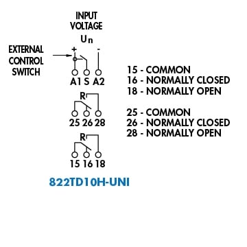
I bought: 822TD10H-UNI Magnecraft 10 Function Programmable Time Delay Relay, 15A DPDT, Universal Coil Voltage 12 - 240 VAC/VDC Specs
FactoryMation told me: You will need to connect a separate power supply to the 822TD10H-UNI for control power. This power supply voltage( 12~240V AC/DC) needs to be connected to terminals A1 & A2.
When energized the normally open set of contacts between terminals 15 & 18 will close. You will use this open set of contacts to switch the voltage required by your load.
The timing signal needs to be a dry contact (no external voltage) between terminals S & A1.
After a follow-up question by me, he said: In order for the timer to work, the voltage that is applied to terminal A1 needs to be connected to terminal S, typically through some type of external switch.
Then after a further question by me he said: Yes, A1 & A2 are used to power the timer.
You CANNOT use an external voltage to control the timer. The S input must be connected to the A1 input (through a switch or a relay contact) to start the timing sequence.
This time-delay is where things really got confusing for me I figured that the time-delay relay needed a separate power source even after the 5-second signal had stopped (that makes sense, so it can keep counting down). But hes saying now that it has to be the SAME power as the Signal? That part I just dont understand. (In his first answer, he even said you will need to connect a separate power supply for control power.)
Heres my drawing of the various components, with my attempt at the wiring.
If anyone could give me the correct wires to connect, I would be so appreciative!!
Does polarity matter on 13 and 14? Did I get the polarity right on all the other wires?
Do the 9&5 pair and 15&18 pair care which terminal of the pair is the input and which is the output? Or is there a protocol for that?
(I decided to buy Double-Pole relays so that I could eventually expand the controlled functions, once I started to realize how cool relays are! But right now Im just looking to control one function for each of the relays -- feed the door strike from one, and turn the lights on for 10 minutes with the time-delay relay.)
Thanks in advance for helping me get this project back down off the shelf!
John

I think Ive bought all the parts I need, but Ive managed to completely confuse myself when it comes to a couple of the wires
------------
Access Control Unit: I have an RFID Access control unit (where you swipe an Radio-Frequency ID tag near the reader to gain access into the building). Once it verifies that it's a valid tag, I want to trigger 2 things -- (1) buzz the electric door strike for a few seconds to unlock the door, and (2) turn on the lights in the room for a period of about 10 minutes.
It's an off-brand access control unit (but it had most of the features I was looking for at a good price), and it seems to be made by KAWA, model #MG236C. The unit and its built-in Lock Relay output are 12VDC. Its already programmed to buzz the strike for approx 5 seconds.
The manufacturer told me to connect the 12V +ve and Ground from power supply to the +12V and GND terminal respectively. Then if you have NO type strike, connect to the NO and DGND terminal.
------------
Door Strike:
The door strike is 16-24VAC. I have a doorbell transformer that can put out that voltage.
------------
Relay to feed Door Strike:
I bought from factorymation.com this relay:
782XBXM4L-12D Magnecraft Electromechanical Relay, "Ice-Cube" Style, 16A DPDT, 12VDC Coil Specs
And the socket for it:
70-782D-1 Magnecraft Relay Socket, 8-pin Cube Style, 2 Pole, 16A, 300V, IP 20 (Finger-safe) Specs
FactoryMation told me: The 782XBXM4L-12D relay requires a 12VDC signal between terminals 13 & 14 (referred to as the coil) to energize.
When energized the normally open set of contacts between terminals 9 & 5 will close. You will use this open set of contacts to switch the voltage required by your load.
------------
Time-Delay Relay to feed regular 120VAC lighting circuit:
I bought: 822TD10H-UNI Magnecraft 10 Function Programmable Time Delay Relay, 15A DPDT, Universal Coil Voltage 12 - 240 VAC/VDC Specs
FactoryMation told me: You will need to connect a separate power supply to the 822TD10H-UNI for control power. This power supply voltage( 12~240V AC/DC) needs to be connected to terminals A1 & A2.
When energized the normally open set of contacts between terminals 15 & 18 will close. You will use this open set of contacts to switch the voltage required by your load.
The timing signal needs to be a dry contact (no external voltage) between terminals S & A1.
After a follow-up question by me, he said: In order for the timer to work, the voltage that is applied to terminal A1 needs to be connected to terminal S, typically through some type of external switch.
Then after a further question by me he said: Yes, A1 & A2 are used to power the timer.
You CANNOT use an external voltage to control the timer. The S input must be connected to the A1 input (through a switch or a relay contact) to start the timing sequence.
This time-delay is where things really got confusing for me I figured that the time-delay relay needed a separate power source even after the 5-second signal had stopped (that makes sense, so it can keep counting down). But hes saying now that it has to be the SAME power as the Signal? That part I just dont understand. (In his first answer, he even said you will need to connect a separate power supply for control power.)
Heres my drawing of the various components, with my attempt at the wiring.
If anyone could give me the correct wires to connect, I would be so appreciative!!
Does polarity matter on 13 and 14? Did I get the polarity right on all the other wires?
Do the 9&5 pair and 15&18 pair care which terminal of the pair is the input and which is the output? Or is there a protocol for that?
(I decided to buy Double-Pole relays so that I could eventually expand the controlled functions, once I started to realize how cool relays are! But right now Im just looking to control one function for each of the relays -- feed the door strike from one, and turn the lights on for 10 minutes with the time-delay relay.)
Thanks in advance for helping me get this project back down off the shelf!
John