Which pass transistor for MC34063?

Thread Starter

electronwaster

Joined Feb 7, 2012
6
Hi,

I'm trying to build a boost converter using an MC34063 (I already bought a bunch of these cheap jellybean converters), and my PSU specs are as follows:
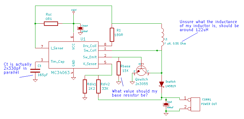
12-15V input
19V output at 2A

Now the high current is the issue, and I'm certain that I'll need a pass transistor, but the MC34063 datasheet doesn't specify which type of transistor or how much power dissipation it has to handle, etc.

Can anyone give me some advice on how to choose a suitable transistor please?

Thanks,
electronwaster
 

Thread Starter

electronwaster

Joined Feb 7, 2012
6
Thanks Wayneh for your reply.

I have seen that AN920/D document already, and the example circuits don't seem to show any use of this chip in boost mode with a pass transistor. Figures 26 and 27 are the only step-up examples for this particular chip, and they both use low current and no pass transistor. They do show a uA78S40 pushing 1000mA in figure 31, but that chip appears to be totally different.

Load conditions for my application would be fairly stable current draw, 2A maximum continuous, often 1A or less, but I'm happy to just aim at 2A.

Operating frequency would be as fast as the chip can go.

There still doesn't seem to be any official guidance/formulae/calculations on the transistor parameters at all, nor does anyone in forum-land (I've tried a couple of others too) have any intuitive guidance. How do people usually work it out?

Thanks,
electronwaster

Edit:

PS: I found this other application note too:

http://www.ti.com/lit/an/slva252b/slva252b.pdf

But that document doesn't seem to have the necessary info either - unless I am missing something.
 
Last edited:

IMAT

Joined Dec 21, 2011
2
Thanks Wayneh for your reply.

I have seen that AN920/D document already, and the example circuits don't seem to show any use of this chip in boost mode with a pass transistor. Figures 26 and 27 are the only step-up examples for this particular chip, and they both use low current and no pass transistor. They do show a uA78S40 pushing 1000mA in figure 31, but that chip appears to be totally different.

Load conditions for my application would be fairly stable current draw, 2A maximum continuous, often 1A or less, but I'm happy to just aim at 2A.

Operating frequency would be as fast as the chip can go.

There still doesn't seem to be any official guidance/formulae/calculations on the transistor parameters at all, nor does anyone in forum-land (I've tried a couple of others too) have any intuitive guidance. How do people usually work it out?

Thanks,
electronwaster

Edit:

PS: I found this other application note too:

http://www.ti.com/lit/an/slva252b/slva252b.pdf

But that document doesn't seem to have the necessary info either - unless I am missing something.
Hi everyone.
I also have same problem. My application requires more than 1A output @ 20V but the chip will not go that high because current limitation at the inlet will be over that. I see many application notes that shows external driver but did not manageto make it work . Best would be a Fet, but it is more difficult for me. The chip works perfect lower than that. Have nothing to say against.

I any help I d appreciate.

Thanks
Mat
 

Thread Starter

electronwaster

Joined Feb 7, 2012
6
Hi Mat,

Hi everyone.
I also have same problem. My application requires more than 1A output @ 20V but the chip will not go that high because current limitation at the inlet will be over that. I see many application notes that shows external driver but did not manageto make it work . Best would be a Fet, but it is more difficult for me. The chip works perfect lower than that. Have nothing to say against.

I any help I d appreciate.

Thanks
Mat
I haven't tried to breadboard anything yet, but as I said before, I have bought a bunch of these converters, so what I might try is to parallel 2 circuits (or more) up, and see whether I can get sufficient current that way.

It would probably need some very small (0.1 ohm or something) current sharing resistors on the outputs, to stop one circuit trying to provide more load than another.

I don't know anything at all about switchers, but maybe some other components could even be shared to simplify things (filter caps, inductors, etc - who knows!?)

electronwaster
 

IMAT

Joined Dec 21, 2011
2
Hi Mat,


I haven't tried to breadboard anything yet, but as I said before, I have bought a bunch of these converters, so what I might try is to parallel 2 circuits (or more) up, and see whether I can get sufficient current that way.

It would probably need some very small (0.1 ohm or something) current sharing resistors on the outputs, to stop one circuit trying to provide more load than another.

I don't know anything at all about switchers, but maybe some other components could even be shared to simplify things (filter caps, inductors, etc - who knows!?)

electronwaster
I can use 34163 for 3.4 A input, but I would have no space for that, as it is twice as big "at least". Well, lets see if some Guru could help us..
Thanks

Mat
 

Thread Starter

electronwaster

Joined Feb 7, 2012
6
I've not used the 34163 myself.

I tried breadboarding up some MC34063 circuits last night, and got the basic circuit to work, and was able to draw around 0.5A from the 19V output with no issues, the voltage was moving around quite a lot under load, but I'm just using a junk-box inductor and I have no idea how many Henries it is.

I tried decoding the diagram in the MC34063 datasheet where the external NPN transistor is used for extra current, and I think I ended up (silently) blowing a couple of transistors. I tried with a BC548 (a small general purpose NPN), and also with a 2n3055 (a large power NPN). they both gave me a really poor output voltage, something like 9V, and when the transistor blew, it started drawing about .7A, so I shut it off quickly. I also blew an MC34063 chip somehow.

I found the following calculators:

http://dics.voicecontrol.ro/tutorials/mc34063/
(this is the one I used last night)

http://www.nomad.ee/micros/mc34063a/
(not tried the output of this calculator yet)

http://www.rau-deaver.org/MC34063_boost.html
(not tried this yet)

http://www.onsemi.com/pub/Collateral/MC34063 DWS.XLS
(played with this, and it gives different results to the one I tried - this one is official)

I think I need a way to make inductors of a specific inductance.

Please reply if you have any more information. One thing I'd really like to know is the value of the base-resistor for the external switch, the diagram doesn't show anything. I tried both 1K and 15K last night. The other thing I think I have worked out is that the lower three unconnected pins in the external NPN switch diagram (4, 5 and 6), should probably be connected as they were originally - without these, nothing useful happens.

electronwaster
 

wayneh

Joined Sep 9, 2010
17,498
I tried with a BC548 (a small general purpose NPN), and also with a 2n3055 (a large power NPN). they both gave me a really poor output voltage, something like 9V, and when the transistor blew, it started drawing about .7A
You won't get much more help without posting a schematic of what you're doing. Your results would likely have been predicted by someone here if they had seen your plan beforehand.
 

Thread Starter

electronwaster

Joined Feb 7, 2012
6
Hi wayneh and others,

Sorry - I should have thought to post a schematic. I just drew this in KiCAD - hope it shows up okay on the page here:


If not, try clicking here: http://i.imgur.com/obgUc.png

I must have had an error in my circuit originally, because the transistor stopped measuring as a pair of diodes on the multimeter (it was a general purpose signal transistor).

After rechecking the breadboard, and switching to a larger 2n3055 power NPN, I can now get my 19V out (both with and without the external switch attached), but when I try to draw an amp or more, it gives me about 0.6A and the voltage droops to 14V. This is approximately what the chip could provide with no external switch.

I have made sure the power source for the circuit can provide plenty of current, but the MC34063 still decides to stop drawing power at about 2.5A. After some brainstorming, I think I may have some kind of transistor-gain problem, or maybe the switching speed isn't high enough, maybe the inductor is too small, maybe the diode isn't fast enough or something. Who knows!

I bought some 25mm ferrite toroids and some 1mm enamelled wire today. I will make some random inductors to try out, but I have no LCR meter, so it will really be guesswork only.

My main question now is what (else) could be causing the restricted current output?

Thanks,
electronwaster

PS: In case it helps me to provide you with data to help debug this problem, I have a good multimeter (no inductance measuring though) and a 20mhz dual-channel scope and various power sources. No function generator yet, unfortunately.

PPS: In case it helps others, I found the following site that has MC34063 information and looks good (I've not read it yet though): http://jiggerjuice.info/electronics/projects/power/mc34063.html
 

wayneh

Joined Sep 9, 2010
17,498
I can't claim to understand your circuit but I see one problem: There's no resistor to limit the base current on your 2N3055. A rule of thumb is that the base current will be 1/10th of the load current. If you don't limit it to that, it can go much higher. I'd consider replacing the BJT 2N3055 with a MOSFET. These transistors don't require a base current, just a voltage on the gate.
 

Thread Starter

electronwaster

Joined Feb 7, 2012
6
Hi wayneh, good catch. I'll try that out today at some point. I had it in my head that Rbase was doing that job (resisting base current), but it's not at all, now that I think about it. I wonder why the application notes don't specify a MOSFET? Ah well, I will try it and see what happens.

Thanks,
electronwaster
 
Top