What's With These Inconsistent Pins?

Thread Starter

Max Holdcroft

Joined May 12, 2024
37
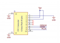
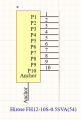
I'm looking at the datasheet for the ISP_1507 BLE module. In the reference schematic for the module, they use a 10 pin 0.5mm pitch FFC, but for the schematic I have the pins are all different. In the example schematic, they have two ground pins, but in my schematic there aren't any, but there IS an additional "anchor" pin? What is this?
I appreciate any help!
Max :)
 

Attachments

Irving

Joined Jan 30, 2016
4,088
No inconsistency. The Hirose connector has 10 signal pins + 2 anchor pins at each end which should be grounded as they form part of a shield around the connector. They're pins 11 & 12 in the first schematic and anchor in the second.

1716812695678.png
 

Thread Starter

Max Holdcroft

Joined May 12, 2024
37
No inconsistency. The Hirose connector has 10 signal pins + 2 anchor pins at each end which should be grounded as they form part of a shield around the connector. They're pins 11 & 12 in the first schematic and anchor in the second.

View attachment 323235
Hey Irving,
Thanks for your response! I'm just a little confused by what you mean. Do you know why there are 2 anchor pins in the first schematic and only one in the second?
 

panic mode

Joined Oct 10, 2011
2,905
schematics may not show everything explicitly all the time... sometimes some things are assumed and not even shown. typical example are power connection for digital chips. and sometimes there are mistakes too. one should be alert and keep an eye on things... and interpret them correctly.
 

Irving

Joined Jan 30, 2016
4,088
Hey Irving,
Thanks for your response! I'm just a little confused by what you mean. Do you know why there are 2 anchor pins in the first schematic and only one in the second?
As pm said above, schematics are short-forms for the real thing. Arguably the first schematic is wrong because it suggests pins 11 and 12 exist though in reality the Hirose connector has only 10pins and the anchors are exactly that, they anchor the connector to the PCB,, and since they are logically one the second schematic is more correct. It is good practice to ground the anchors, though it may not be necessary in all circumstances.

A word of warning. If you've not worked with these connectors before be very careful about assembly. They won't take much abuse and hand-soldering isn't really an option - not saying it can't be done just that hand-soldering tends to end up spraying solder everywhere and the smallest drop on the contacts renders an expensive connector useless Read the datasheet (attached)
 

Attachments

Last edited:

nsaspook

Joined Aug 27, 2009
13,631
As pm said above, schematics are short-forms for the real thing. Arguably the first schematic is wrong because it suggests pins 11 and 12 exist though in reality the Hirose connector has only 10pins and the anchors are exactly that, they anchor the connector to the PCB,, and since they are logically one the second schematic is more correct. It is good practice to ground the anchors, though it may not be necessary in all circumstances.
+1 what the OP sees Is pretty common when the part needs a physical attachment to move stress from the electrical connections to a mechanical Board Lock connection.
DB9 connector example.
https://www.mouser.com/datasheet/2/418/6/ENG_CD_2301826_D-2045688.pdf
1716831360869.png
For the schematic/PCB design program, the shell/Board Lock GND' needs to have some sort of 'pin' type designator for a netlist.
1716831607967.png
1716831669379.png
 
Top