What is this op-amp configuration?

Thread Starter

ECE101

Joined Nov 25, 2011
29
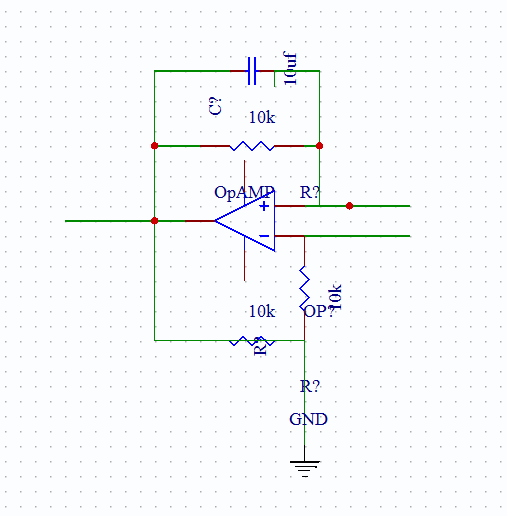
Just wondering if someone could describe the function of the circuit below?


Is it some form of Inductance gyrator?
 
Last edited:

Thread Starter

ECE101

Joined Nov 25, 2011
29
The input is the non inverting input.

I don't think it's a schmitt trigger?

It has negative feedback and also low pass filtered positive feedback?
 

studiot

Joined Nov 9, 2007
4,998
Looks like some kind of filter to me.

Are you sure you have drawn it correctly?

If you had the inputs swopped it would be a classic low pass filter.

With a few extra components it could be a Sallen and Key filter.

Why are there two series 10k resistors in the negative feedback loop with no other connections?
 

#12

Joined Nov 30, 2010
18,224
Without "R Ground" included, it does not have negative feed back, just a 10k input load and a 10k output load. If R Ground existed, it would have a negative feedback path.

I have to say the drawing is incomplete. The 10 uf capacitor reminds me of an integrator, and the 10k in positive feedback reminds me of hysteresis (as in Schmidt trigger) but without an input resistor the results can't be calculated.

It is simply an incomplete circuit.
 

Thread Starter

ECE101

Joined Nov 25, 2011
29
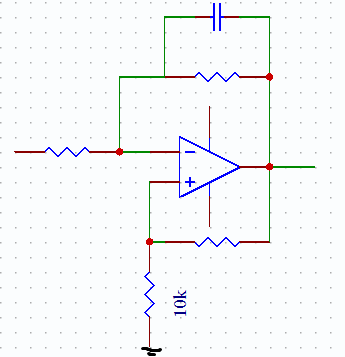
hmmm well if the inputs were swapped:


it would be a low pass filter, but what would be the purpose of the 2 resistors in the non inverting feedback loop?
 
Last edited:

Thread Starter

ECE101

Joined Nov 25, 2011
29
Ah yes good point, but still what would be the purpose of the 2 resistors connected between the output, ground and non inverting input?
 

studiot

Joined Nov 9, 2007
4,998
This is in the homework section.

Is this homework and if so can you scan the original question?

We are still working in the dark here.
 
Top