What happens to U2(t) after Voltage drop of U1(t)?

Thread Starter

Tobias Hildebrandt

Joined Jan 1, 2016
44
Hello,

this information was provided by our Professor:
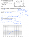
-U1(t) had for long time an initial value of 12 V.
-At t = 0.5 ms the U1(t) drops to 0 V. (You can see that in the graph at the bottom of the page).

Parts A and B I solved by myself and I got the same results as my Prof.
A) U2(t) @ 0 ms? Result: 3 V. Method: Simple Voltage divider.
B) What is the Voltage across the capacitor @ 0 ms? Result 9 V. I just subtracted 12 V - 3 V = 9 V. Is that all I have to do?

I am struggling with part C.
I get the same equivalent circuit and it appears to me, that he uses the Voltage divider formula ( 12 V * R1/(R1+R(TH)) ), but I am not certain (at all) why he does that? The next step is equally puzzling, why is he subtracting 1 V - 9 V?
Is there a different equivilant circuit that I could use?

Tobias Capture29.PNG
 

Attachments

WBahn

Joined Mar 31, 2012
30,057
Since this is an English-only forum, there probably aren't too many people that can read the questions. So you need to provide the translations for (c) and on just like you did for (a) and (b).
 

Thread Starter

Tobias Hildebrandt

Joined Jan 1, 2016
44
Excelltent point! I totally forgot to translate the Question! Sorry about that!

Here is the question: What happens to U2(t) right after the drop of U1(t)?
 

WBahn

Joined Mar 31, 2012
30,057
Hint: Since R1 and C1 are in series, they can be swapped for analysis purposes (that don't involve the voltage at the junction between them, anyway).
 

Thread Starter

Tobias Hildebrandt

Joined Jan 1, 2016
44
Untitled21.png
Is this the equivalent circuit you were talking about? If so, than I understand why he used the voltage divider formula, BUT why do I have to subtract 9 V from 1 V?
 

WBahn

Joined Mar 31, 2012
30,057
No, that's not what I was talking about. I was talking about swapping R1 and C1 to (potentially) make things a bit easier to visualize.

What he has done is replace everything to the right of node 2 with it's Thevenin equivalent.

Also, if the blue 9V is the instructor's answer for (b), then the instructor might need to pay more attention to the specified polarities of the signals. Unless I am mistaken (and it's possible, since I seldom us arrow conventions for voltages instead of + and - labels), the arrow above the capacitor means that the voltage on the right side of the capacitor is greater then the voltage on the left side of the capacitor whenever Uc1 > 0.
 

Jony130

Joined Feb 17, 2009
5,488
Unless I am mistaken (and it's possible, since I seldom us arrow conventions for voltages instead of + and - labels), the arrow above the capacitor means that the voltage on the right side of the capacitor is greater then the voltage on the left side of the capacitor whenever Uc1 > 0.
I don't know why but Germans use different convention. The arrow tip (head) point into the lower potential. Notice how Vth is mark.

Tobias Hildebrandt

Can you solve for U2 for this circuit ?

1.PNG
 

Thread Starter

Tobias Hildebrandt

Joined Jan 1, 2016
44
Untitled32.png
The Helmholtz Method seems to give me the right answer, I think this is what you had in mind, aye?
It seems that my Prof used a different method to calculate the value, but both are equally correct, aye?
In what cases can I transform a capacitor into a voltage source?
 

Jony130

Joined Feb 17, 2009
5,488
I never heard about "Helmholtz Method" but it looks like you are using a superposition theorem.
Do you know the Kirchhoff's voltage law (KVL) ? Can you write a KVL equation for this circuit (a single loop)?
 

dannyf

Joined Sep 13, 2015
2,197
What happens to U2(t) right after the drop of U1(t)?
Easy: the voltage across the capacitor cannot change instantaneously.

Before the voltage drop, the capacitor's right has a potential of 3v; The capacitor's left has a potential of 12v. For a difference of -9v, from right to left.

When V1 changes, that voltage does not change instantaneously.

The rest is easy.
 

WBahn

Joined Mar 31, 2012
30,057
I don't know why but Germans use different convention. The arrow tip (head) point into the lower potential. Notice how Vth is mark.
Wonderful -- all the more reason to avoid that notation (but, of course, if that is what you are taught and/or expected to use...).
 

WBahn

Joined Mar 31, 2012
30,057
The Helmholtz Method seems to give me the right answer, I think this is what you had in mind, aye?
It seems that my Prof used a different method to calculate the value, but both are equally correct, aye?
In what cases can I transform a capacitor into a voltage source?
Like Jony130, I've never heard of "the Helmoltz Method", but it looks like what we refer to as "superposition".

As for transforming the capacitor into a voltage source, that is done because at the instant the change in the circuit is made, the voltage across the capacitor cannot change, which means that it looks like a voltage source at that instant in time.
 

Thread Starter

Tobias Hildebrandt

Joined Jan 1, 2016
44
Capture33.PNG
Question D: Provide a function u2(t) for t > 0.5 ms.

So at this point the capacitor starts to discharge, so I use the formula: u(t) = U(max) * e^( - (t / RC )).

The calculation of the time constant is strait forwart. It is just R times C.

The +3 V comes from the voltage divider.

The - 0.5 ms part in he exponent is rather obvious as well, but where does the - 11 V come from?

It seems that I always ask similar questions, is that sth I can solve with the superposition method?
 

Jony130

Joined Feb 17, 2009
5,488
The general formula for capacitor charging/discharging phase looks like this
Vc = V∞ + (Vo - V∞)*e^(-t/(τ))
And in this formula Vo includes the initial capacitor voltage (-8V).
And V∞ - is a steady state final voltage (+3V)
(Vo - V∞) = (-8V - 3V) = -11V
 
Top