Voltage level Shifter

Thread Starter

SynME

Joined May 21, 2009
5
I have an application similar to mikewilliams, though I need to step a signal from a 0-5VDC and give it a +12VDC step. This is due to creating a split voltage supply from a +24VDC power supply to use as a motor driver. The input control signal (it's for a proportional control valve) shares a common 0VDC with the 24VDC, but it needs to be stepped up to the local +/-12VDC range used to power the control and drive circuits.

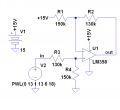
I'm a mech-e, so my grasp of the electronics for this is still developing. How would you go about modifying the circuit above? I'm guessing it has to do with R3 and R4, but not sure how. Or is this just the wrong circuit for this application?

Thread to which SynME has referred.
 
Last edited by a moderator:

Bernard

Joined Aug 7, 2008
5,784
If this is just for simulation, and no current is supplied by +5V tap, then use a voltage divirer. Assume a 5000Ω pot, at 18V current is .0036 A, if slider is set at 1388.89Ω from ground, output will be 5V. 13V translates to 3.611V. Or input V X .2777 = reduced V. Use perfect voltmeter to measure, or use non-inverting OP Amp buffer to supply current.
 

Thread Starter

SynME

Joined May 21, 2009
5
Hmm... Thanks for both replies. I think Ron H got closer to what I was needing. I just downloaded NL5, so I am playing with attempting to simulate the circuit before I build it (strange concept, eh?)

Bernard, here's sort of what the requirement is:

Vin____Vout
0V-----12V
1V-----13V
....
5V-----17V

The idea is to shift the 0 to 5V control signal which uses the 24V common ground, and shift it to the local +/-12V range which is essentially produced from the 24V supply, but is used for actual power applications.

I'll see if I can run the simulation and post the results.
 

Thread Starter

SynME

Joined May 21, 2009
5
Well, I think I got it. This worked both in the simulation, and I was able to test it on my breadboard. Since it's a simple DC signal input, there is really no need for frequency consideration, so I'm not worried if there is any transients that might crop up with this design.


The 12V is generated by the LM675 circuit mentioned earlier.
 

Ron H

Joined Apr 14, 2005
7,063
Hmm... Thanks for both replies. I think Ron H got closer to what I was needing. I just downloaded NL5, so I am playing with attempting to simulate the circuit before I build it (strange concept, eh?)

Bernard, here's sort of what the requirement is:

Vin____Vout
0V-----12V
1V-----13V
....
5V-----17V

The idea is to shift the 0 to 5V control signal which uses the 24V common ground, and shift it to the local +/-12V range which is essentially produced from the 24V supply, but is used for actual power applications.

I'll see if I can run the simulation and post the results.
My circuit was not a solution to your problem. It was for mikewilliams. Apparently you had hijacked his thread.
 

Thread Starter

SynME

Joined May 21, 2009
5
Normal the term "hijacking" refers to going off on a completely different tangent idea from the topic of the post. As my issue was related to his, it seemed logical to keep it in the same thread. Also, since the thread was about 6 months old, I don't think the originator of the thread would really care if some new stuff were added to it.

I'm a little lost why you are bringing this up now. Your circuit was enough of a hint in the right direction that I was able to modify the principal to work for me. Seems hand in hand in my book. My thanks for that help.
 

Ron H

Joined Apr 14, 2005
7,063
Normal the term "hijacking" refers to going off on a completely different tangent idea from the topic of the post. As my issue was related to his, it seemed logical to keep it in the same thread. Also, since the thread was about 6 months old, I don't think the originator of the thread would really care if some new stuff were added to it.

I'm a little lost why you are bringing this up now. Your circuit was enough of a hint in the right direction that I was able to modify the principal to work for me. Seems hand in hand in my book. My thanks for that help.
I have to confess that I didn't realize the thread was old. I don't think I even saw your post. It was probably on the second page, so I missed it. I was not happy with beenthere's solution to mikewilliams's problem, so I designed the circuit i posted. I can see now why you thought I was responding to your post.
But, I am not bringing it up "now". I brought it up almost 2 weeks ago (May 27).
Looking at the posting dates, you are right. Hijacking was not an appropriate accusation. Sorry for the confusion.:(
 

Thread Starter

SynME

Joined May 21, 2009
5
hehe All good. Forums have that whole "time lag" thing, so whenever one sees the latest posts, then of course it happened "now". Anyway, thanks for your help. I swear, when this proportional control valve actually works, I'm going to get drunk in celebration. I think I'll use it to actually pour the beer, though the foaming would be terrible.
 
Top