Voltage Level Shifter Circuit

Thread Starter

mikewilliams

Joined Nov 4, 2008
10
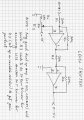
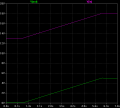
Hi all I am building a circuit that will shift the input voltage (which is an AC voltage pulsing from 13 to 18 volts) down to a pulse of 0 to 5 volts, with very minimal signal loss. I originally thought of using a camparitor circuit, but the output voltages were not what I expected.

I am thinking of using a voltage level shifter, but what would the circuit look like, as I have never built one of those.

Also if you have a better idea other than the two I thought of, feel free to tell me.

Thanks,
Mike
 
Last edited:

beenthere

Joined Apr 20, 2004
15,819
Can you provide some parameters like frequency and repetition rate of the pulse? Is this an RMS voltage, or a DC pulse riding on a DC level? What is "minimal signal loss"?
 

Thread Starter

mikewilliams

Joined Nov 4, 2008
10
Hi the frequency is very very slow, and I'm not sure what you mean on the other part, its basically just a pulse, pulsing between 13 volts, then changing to 18 volts staying there for a while, then going back to 13 volts for a while.

Also what i mean with 'little signal loss' is that when I change the voltage from 18 -> 5 I want it to be really close to 5, not 5.9 for example.
 

beenthere

Joined Apr 20, 2004
15,819
Ok, try this. You will need a dual output power supply for plus/minus 15 volts.

Adjust the offset for 0 volts out at the 13 volt level, and -5 volts out at the 18 volt pulse. The next stage inverts, and the use of a trim pot there can make your gain very accurate.
 

Attachments

Thread Starter

mikewilliams

Joined Nov 4, 2008
10
First of all thank you very much for taking the time to answer my question.

I am new to electronics as you probably can tell, so could you please tell me what R4 and R3's purpose is, and why they are needed. Also I am unsure what a 20T trimmer is if you could just give me a basic explanation of what it does and why its needed.


Thanks!
Mike
 

beenthere

Joined Apr 20, 2004
15,819
R3 is tied to -15 volts at one end. R4 keeps current to circuit ground low (I = E/R). The span of voltage across R3 will be 2.5 volts (E = IR), so you can set the offset very closely.

A trimmer is a small potentiometer that has a screwdriver adjust - usually from 15 - 25 turns. Look up part #T18-5.0K on the Digi-Key site.

The first op amp section inverts the signal and applies an offset to make the signal level 0 with the 13 VDC input. The second section reinverts it. That seems busy, but it's a convenient way to add an offset voltage to an existing signal.

You would want to use 1% resistors. R4 should really be 24.9K. 1/4 watt is good for dissipation (the amount of heat wasted in each resistor).

Hope you have a meter to use to set the offset and gain?
 

Thread Starter

mikewilliams

Joined Nov 4, 2008
10
I am actually going to be simulating this using some flavor of spice. I am trying to analyze this circuit by hand first though, but am having a little trouble. What is the voltage for R2, is it -10.5V? If so then I seem to understand it.

Sorry once again, but I am just beginning electronics.

Thanks
Mike
 

beenthere

Joined Apr 20, 2004
15,819
The current through R1 is opposed and canceled by the current (of opposite sign) through R2. Same for R5 & 6. For 13 volts at the input, the current in R1 is 650 microamps. The same goes through R2, so the voltage drop across R2 is -13 volts.
 

Ron H

Joined Apr 14, 2005
7,063
Beenthere, you, or someone, moved my solution to mike's problem to a new thread. Perhaps you could move or copy it back to this one.

EDIT: Below is the solution I proposed on May 21, which was erroneously moved to another thread.
 
Last edited:

David Bridgen

Joined Feb 10, 2005
278
Conect a 13V zener and a resistor in series across your pulsing voltage, zener's cathode to the voltage, other end of resistor to 0V.

With 13V across them there will be 0V, or nearly 0V, across the R.

When the input voltage increases to 18, there will be 13V across the zener and 5 across the R.

Take your ouput from across the R.
 
Top