
I'm playing around with eagle trying to learn how to use it because I think it might be better for PCB design than ultiboard.
I wanted to build this circuit (found here) in eagle and mess around with the PCB (also, I want to use this circuit)
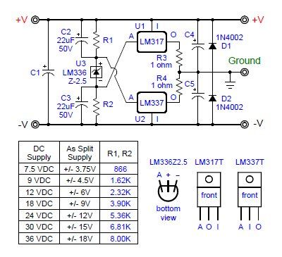
According to the chart, if I change the input voltage, I need to change R1 and R2 to get the desired output voltage.
What are the calculations to determine the values of R1/R2 for the "as split supply" voltages. I.E, if I had 866Ohm resistors, but was feeding it 12V, what would the "as split supply" be?
Secondly, would there be a way to automatically adjust the values of R1/R2 instead of using resistors, so that if the input voltage changed, the correct resistance would be selected.
I would have it connected to my bench PSU, which is infinitely adjustable 0-30V.
I wanted to build this circuit (found here) in eagle and mess around with the PCB (also, I want to use this circuit)
According to the chart, if I change the input voltage, I need to change R1 and R2 to get the desired output voltage.
What are the calculations to determine the values of R1/R2 for the "as split supply" voltages. I.E, if I had 866Ohm resistors, but was feeding it 12V, what would the "as split supply" be?
Secondly, would there be a way to automatically adjust the values of R1/R2 instead of using resistors, so that if the input voltage changed, the correct resistance would be selected.
I would have it connected to my bench PSU, which is infinitely adjustable 0-30V.


