Hello evryone,
Im currently doing an electronics project and in this project I was given a colpitts oscillator which operates at 100Khz. But I need to modify this circuit so that it can give sine waves with variable frequencies. The inductor coil is constant and I can only change either of the 2 capacitors to get variable frequencies.
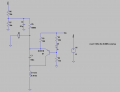
So I decided to fix one of the capacitors at 150nF and replace the other capacitor with a Varactor or a variable capacitor. The capacitance of the varactor is changed by the use of a potentiometer as shown in the LTspice schematic attached.
However, the circuit has stopped to oscillate now. Im not sure where i went wrong. Any suggestions are greatly appreciated")
Im currently doing an electronics project and in this project I was given a colpitts oscillator which operates at 100Khz. But I need to modify this circuit so that it can give sine waves with variable frequencies. The inductor coil is constant and I can only change either of the 2 capacitors to get variable frequencies.
So I decided to fix one of the capacitors at 150nF and replace the other capacitor with a Varactor or a variable capacitor. The capacitance of the varactor is changed by the use of a potentiometer as shown in the LTspice schematic attached.
However, the circuit has stopped to oscillate now. Im not sure where i went wrong. Any suggestions are greatly appreciated
Attachments
-
2.2 KB Views: 164