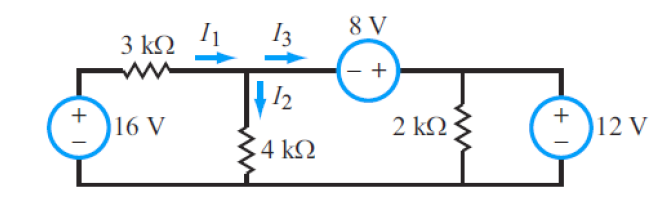
I don't see it. My textbook says that devices are in series when the current only has one pathway to travel through. If I1 splits into I2 and I3, then how exactly are the voltage sources in series?
If that doesn't help your understanding, then put aside the idea of a series connection for the moment ....
From the lower conductor [reference potential / ground], consider what rise or fall in potential you see as you move through the two sources [12V & 8V]. So starting from 0V at the common, as you pass through the 12V source the potential rises to +12V, at the node where the two sources and the 2kΩ meet. As you pass on through the 8V source towards the other node, the potential will fall by 8V. So, you go from +12V down to +4V, at the left-hand node where the 3kΩ, 4kΩ and 8V source [-ve] terminal meet.
In effect, you could take the the result as the same as the algebraic addition of the two sources to obtain the result of +4V at the left-hand side node. So the result is the same as you obtain with series connection of the sources with the polarity orientations shown.
The rest is simplicity itself, with a potential difference of 12V across the 3kΩ and 4V across the 4kΩ. This will lead to the currents I1 & I2 and on to I3 from KCL.
I don't see it. My textbook says that devices are in series when the current only has one pathway to travel through. If I1 splits into I2 and I3, then how exactly are the voltage sources in series?
They aren't, at least not strictly speaking. But Austin and mlog are correct as far being able to leverage them almost as though they are. The key to understanding this is that an ideal voltage source will generate whatever current is necessary in order to maintain the specified voltage across it, so it doesn't matter that they don't have the same current. As long as they are connected to each other directly, then you can directly determine the voltages at the nodes involved (at least relative to each other). What you can't do, and which makes them so that they can't really be treated as though they were in series, is assume anything about the current in one even if you know the current in one of the others.
Look at your diagram again. You have four nodes. One of them you get to call 0V (you can pick any one you want). From there, you can directly give the node of any voltage that is connected to that node via a voltage source. Once you have those nodes given, you can do the same for any and all nodes connected to them via a voltage source. In this case, all four of your nodes can be solved for just based on the voltage sources. To see this more formally, do KVL on the outer rim of the circuit and what do you end up with: one equation and one unknown (the current in the 3ohm resistor)! Do it about the rightmost loop (the 12V source and the 2ohm resistor) -- again, one equation and one unknown! Now, can you find a loop that goes only through voltage sources and the 4ohm resistor?
I don't see it. My textbook says that devices are in series when the current only has one pathway to travel through. If I1 splits into I2 and I3, then how exactly are the voltage sources in series?
Your book isn't wrong. It's just incomplete. It's not telling you the whole story. If 2 voltage sources are end to end, they're in series. Your book is correct in terms of resistances in series. If you are to combine 2 resistors in series, neither can be in parallel with another resistor. But we aren't talking about resistors. We are talking about voltage sources. The rules are different for voltage sources.
In your example, begin at the node of I1, I2, and I3, and move to the right and pass through the 8V source. Continue clockwise around the outer loop. Next you pass through the 12V source. Keep going clockwise and you pass through the 16V source. So, the 8V is touching the 12V is touching the 16V. They're all 3 in series. It doesn't matter that the 2k resistor is in parallel with the 12V source. The 12V is still in series with the 8V and the 16V.
I'm not quite following what you're doing. To calculate the voltage around the entire loop, you don't need to worry at all about current. Just pay attention to the polarity and voltage of the individual sources, and calculate from there.
Your problem is that you aren't using the labelled currents consistently. I2 is the current flowing down through the 4kohm resistor, but in your second equation you use it as the current flowing down through the 2kohm resistor. Then in the next equation you use the I2 that you solved for using the 2kohm resistor as though it really were the current in the 4kohm resistor. Can't do that!
Your first equation is fine, except for the units. I1 is not 4 (saying that a current is "4" is meaningless. That;s like saying the distance between two cities is 245. I1 is 4mA.
Your second equation is only correct if I2 is the current flowing down in the 2kohm resistor, which it isn't. There is no label provided for this current, so define one! I4 is hereby the current flowing downward through the 2kohm resistor. So you have I4 is 6mA.
Your third equation involves an unknown, namely I2. So you will use that equation to solve for I2. With I2 in hand, you can then apply KCL to the node at the top of the 4kohm resistor to find I3. With I3 and I4, you can apply KCL to the node at the top of top of the 2kohm resistor to find the current in the 12V supply (let's call it I5).
As a check, you can do KVL around the inner loop to see if it works out.
We cross posted, so this response is a bit dated, but I thought it important to point out that the answer is, "No, because the voltage around ANY loop (talking conservative fields here) is 0V!" That's what KVL is based on.
Instead, ask your quesiton like. So, is the voltage drop from Point A to Point B 12V?
Yes! So the 6mA in the 2kohm resistor is coming equally from the two supplies it is connected to.
Note that, when it's an option, we generally try to use the 'passive sign convention', which means that we pick the directions of our currents so that they flow out of the positive terminal of a voltage source. But you can pick which every you want as long as you are careful to properly track the resulting minus signs. For instance, if asked to compute the power delivered by the 12V source, it would be (-I5)(12V).
I would recommend starting a new thread for the new circuit. People expect the problem statement to be at or near the top of the thread and if it gets lots of responses late comers will often jump to the top of the thread, read the problem, and then jump to the end assuming that that is the problem being discussed. Since many circuit problems will use the same variables, it is hard to determine that you are seeing a different problem being worked as opposed to the original problem simply being worked incorrectly.

 Facebook
 Google
 GitHub
 Linkedin