Hi All,
I'm trying to interface the STM32F4 Discovery board with an AC Servo drive (Hiwin D2 Drive + Mige 130ST-M10010 AC servo motor).
Here is the link to the servo drive manual https://www.hiwin.com/pdf/d2_drive_user_manual.pdf
So basically, I have this hex file of a closed source firmware, whose function is to, on one side, interface with PC through USB port, and on the other side, send PWM + DIR signal to control a servo motor drive, operating in torque control mode. PC communicate with STM32F4 the torque level it wants, STM32F4 send PWM + DIR signal to drive as a reference signal, servo drive driving the motor to generate torque accordingly.
Here's how the whole system looks like. Note that i'm not using the Drive named Argon, but using Hiwin D2 instead.


Following diagrams are all I have from the author of this firmware.


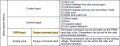
There are different control mode that STM32F4 can output, I decide to go with PWM + DIR (bottom left)
So output signal pin for PWM is PE9 and DIR is PE11.
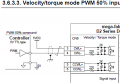
Now, i've dug through the servo drive manual, and below is the closest thing in terms of wiring I can find from the manual

My concern is, as you can see here, the manual mentions 5V TTL type controller as a sample. However, if I'm not wrong, output from PE9 and PE11 are 3.3V CMOS signals, therefore, I do not know whether I can follow this wiring instruction to link up the STM32F4 to the servo drive.
So my question is
What is the logical signal that comes out of PE9 and PE11 pin? (what logic level type)
Is there a difference in wiring for a 5V TTL PWM signal and 3.3V CMOS PWM signal?
Can someone also please explain to me the wiring configuration above (why is a 5VDC source needed to connect to + terminals? STM output connected to - terminal?) and what is the purpose of the internal wiring of the Servo drive (before the optocoupler)?
I asked the above question because last time when I played around with Arduino board, the connection is usually this way:
PWN pin to + terminal
GND pin to - terminal
There's not extra 5VDC needed.
Thanks in advance and if there is anything point which I did not make clear, please dont hesitate to clarify with me.
Cheers!
I'm trying to interface the STM32F4 Discovery board with an AC Servo drive (Hiwin D2 Drive + Mige 130ST-M10010 AC servo motor).
Here is the link to the servo drive manual https://www.hiwin.com/pdf/d2_drive_user_manual.pdf
So basically, I have this hex file of a closed source firmware, whose function is to, on one side, interface with PC through USB port, and on the other side, send PWM + DIR signal to control a servo motor drive, operating in torque control mode. PC communicate with STM32F4 the torque level it wants, STM32F4 send PWM + DIR signal to drive as a reference signal, servo drive driving the motor to generate torque accordingly.
Here's how the whole system looks like. Note that i'm not using the Drive named Argon, but using Hiwin D2 instead.
Following diagrams are all I have from the author of this firmware.
There are different control mode that STM32F4 can output, I decide to go with PWM + DIR (bottom left)
So output signal pin for PWM is PE9 and DIR is PE11.
Now, i've dug through the servo drive manual, and below is the closest thing in terms of wiring I can find from the manual
My concern is, as you can see here, the manual mentions 5V TTL type controller as a sample. However, if I'm not wrong, output from PE9 and PE11 are 3.3V CMOS signals, therefore, I do not know whether I can follow this wiring instruction to link up the STM32F4 to the servo drive.
So my question is
What is the logical signal that comes out of PE9 and PE11 pin? (what logic level type)
Is there a difference in wiring for a 5V TTL PWM signal and 3.3V CMOS PWM signal?
Can someone also please explain to me the wiring configuration above (why is a 5VDC source needed to connect to + terminals? STM output connected to - terminal?) and what is the purpose of the internal wiring of the Servo drive (before the optocoupler)?
I asked the above question because last time when I played around with Arduino board, the connection is usually this way:
PWN pin to + terminal
GND pin to - terminal
There's not extra 5VDC needed.
Thanks in advance and if there is anything point which I did not make clear, please dont hesitate to clarify with me.
Cheers!
Last edited: