Using a 24V Peltier to heat and cool a couple of L of water

Thread Starter

n33”

Joined Mar 20, 2022
12
Hi all, hope everyone is OK

I think this has been asked at nauseam and I have done my utmost best to trawl through what I can find.

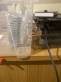
I have a 24V 200W peltier which I wish to use to cool or heat a very small amount of water, circa 2-3L

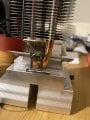
I have a 12V 100w fan with a heatsink and I have a huge heatsink and another fan.

i also have an aluminium and a copper cooling block (not entirely sure on how to incorporate these either)

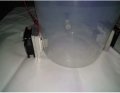
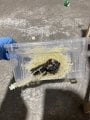
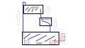
Im not entirely sure how I should be approaching this…my current logic is if I seal the huge heatsink in the water (plastic container) with the peltier on the outside and attach the fan to that and power peltier through two channels of a 4 channel SPST relay, I should be able to reverse the polarity and have the peltier transfer heat to the water via the inner heatsink.

Will this even work?

I want to connect the relay to an arduino and have a temperature sensor in the water with a few buttons in order to select the temp and start the heating or cooling cycle to desired temp.


Please bear with me as I am a noob and will require some explaining to akin to a schoolchild

I hope this makes sense. I would highly appreciate any pointers anybody can give me and thank you all in advance :)
 

MrChips

Joined Oct 2, 2009
30,821
Welcome to AAC!

2-3L of water is a significant amount for that size TEC.
What is your primary objective, to heat or cool the water?
What is your target temperature or range of temperatures?
 

Thread Starter

n33”

Joined Mar 20, 2022
12
Welcome to AAC!

2-3L of water is a significant amount for that size TEC.
What is your primary objective, to heat or cool the water?
What is your target temperature or range of temperatures?
Thank you for the warm welcome and the speedy reply!

I would like to do both; primary objective is to keep the temperature of water constant at a user set point. I would like to demonstrate decreasing and increasing of temperature.

I initially thought to use a kettle element at 230VAC wired to relay and use arduino to cycle that on/off for heating if user setpoint is greater than water temp or to activate peltier if setpoint is above, but it got real messy real quick splicing into all wires etc. and I don’t really fancy killing myself as I could see happening if I carried on that way…

I forgot to mention I also have a small mains pump which I wish to active once temperature reaches set point. The only way I can really see personally to incorporate this is to wire it to relay which is connected to arduino and use the temp sensor to switch it. That’s fairly simple I think (I am completely open to better and more efficient ideas and being told I’m a moron!!)

The target temp is to maintain steady at 37 deg C, not too fussed about pinpoint accuracy can give take a few degrees. But I would like for it to have some user - based functionality outside of that range, within reason. I don’t expect the water to be reaching 0 deg or above 50 with a single module at all and It’s not what I’m looking to do
 
Last edited:

MrChips

Joined Oct 2, 2009
30,821
Even though a TEC can be used for both cooling and heating it is not very efficient at heating when compared to an ordinary heating element.

You want the active side to be in good thermal contact with your water vessel.
I would imagine that a metallic vessel and a copper plate in good contact with the TEC would be preferred.
In cooling mode, the hot side of the TEC must be mounted to your forced air cooled heat sink.

In heating mode, the cold side of the TEC will get very cold. Efficiency diminishes as the temperature differential increases. Remember, this is a heat pump. You are pumping thermal energy from one side to the other. Blowing room temperature air on the cold side will assist in rising the temperature.

1647804632517.png
 

Thread Starter

n33”

Joined Mar 20, 2022
12
Even though a TEC can be used for both cooling and heating it is not very efficient at heating when compared to an ordinary heating element.

You want the active side to be in good thermal contact with your water vessel.
I would imagine that a metallic vessel and a copper plate in good contact with the TEC would be preferred.
In cooling mode, the hot side of the TEC must be mounted to your forced air cooled heat sink.

In heating mode, the cold side of the TEC will get very cold. Efficiency diminishes as the temperature differential increases. Remember, this is a heat pump. You are pumping thermal energy from one side to the other. Blowing room temperature air on the cold side will assist in rising the temperature.

View attachment 263301
Do you think I should stick with the kettle element and stick to peltier for cooling?

The only reason I explored this route is currently I have 3 separate power supplies and a bunch of spliced wires all of the place through 2 relays and it’s just very, ugh.

and also I am currently using a plastic box which is quite small and the element is in quite proximity to the pump so I may end up melting the pump and the box around it, spilling water out onto mains voltage, you know how it goes from there…

I absolutely understand the absence of efficiency of these modules. My primary aim is not efficiency it’s more of the control side that I am interested in.

would I still be able to proceed with a plastic vessel? I have been given set components and have little room for wiggle and a small budget to order electronic components which may or may not be needed.

if you look at the image below and If the desk below represents the water the card in between represents the peltier and the fan (both of which are outside the vessel), would this work?

if you see second image, they’ve used one for heating one for cooling, I’m going for something like that but if I can dissipate heat to water then I think it’ll do what I need it to do…(please tell me if you disagree)

Are you saying to add a al or cu plate above (where my ID card represents peltier) in between the fan heatsink pipes like in your diagram?

im very sorry but I may be even more confused now… won’t the heat sink I’m using do the same thing as the copper plate?

I apologise again for what may be seem like silly questions and thank you again for bearing with me and for taking the time out to help me
 

Attachments

Thread Starter

n33”

Joined Mar 20, 2022
12
Are you doing to use the Arduino to create a PID controller?
should I do PID if im using a SPST SSR relay? As far as I understand arduino would be used to measure temp and flick relay coils via signal

not exactly sure how I would even do PID or if I need any kind of other circuitry etc.
 

Ya’akov

Joined Jan 27, 2019
9,170
If you don't use PID you will at least have to use hysteresis to avoid rapid cycling. But you can use PWM to implement PID and it will work far better than a simple hysteresis system.
 

Thread Starter

n33”

Joined Mar 20, 2022
12
If you don't use PID you will at least have to use hysteresis to avoid rapid cycling. But you can use PWM to implement PID and it will work far better than a simple hysteresis system.
Thank you for the reply. I’m taking this to mean I can implement some form of PID with PWM even though im using the relays to switch the polarity? I’ve read online that this shouldn’t be done but in all honesty, I’m out of my depth with the electronics side and I’m doing my best to understand, but a lot of is just going over my head :(

My logic thus far is as follows; user set temp of 35degC when water temp is 25 deg C -> peltier hot side inside tank. When water temp reaches say 33, turn peltier and fan off and vice versa; if temp is 35 deg C and user set to 25, switch cold side inside of tank connected to big metal heatsink and hot side it outside connected to fan and switch off at about 27/28 deg

could you please point me in the right direction of how I would do the PID programming? I can provide bill of materials of whatever I have so far if it’s relevant

I’m going to hook up the peltier with relays tomorrow and start testing it, I’m not entirely sure if it’s even going to work ( reassurance please?! ) the last thing i want is to burn the module out.

could you please elaborate on what you mean by using hysteresis to avoid rapid cycling?

I’ve attached again a quick image of how this is looking in my head…the peltier will be sandwiched in between the two ensuring none of it is in contact with the plastic to make sure it doesn’t melt it. I would change the container if I could but I can’t.

Sorry for sounding like a broken record lmao, just stressed cos I’ve been bouncing this problem around in my head for a while and have not made any progress at all.

thank you again
 

Attachments

Last edited:

Ya’akov

Joined Jan 27, 2019
9,170
First of all, is it a requirement to switch between heating and cooling? Do you have a specification for how fast the water has to be able to be changed in temperature by the user? Also, what is the permitted range?

Using the Peltier is already fraught, it is much worse at heating for the same power input than a resistor. You could cool with is and heat with a resistor submerged in the water with far less current. You can't beat resistive heating for efficiency.

I don't expect you will burn out the module, but I will be surprised in 2-3l of water change temperature fast enough for your purpose.
 

MrChips

Joined Oct 2, 2009
30,821
If your target is above room temperature I would skip the TEC and use an immersion heater.
PID control is not difficult to do, We can help you with that. In fact just PI control works well for controlling temperature of water baths.
I would use a solid-state relay instead of a mechanical relay.
 

Thread Starter

n33”

Joined Mar 20, 2022
12
First of all, is it a requirement to switch between heating and cooling? Do you have a specification for how fast the water has to be able to be changed in temperature by the user? Also, what is the permitted range?

Using the Peltier is already fraught, it is much worse at heating for the same power input than a resistor. You could cool with is and heat with a resistor submerged in the water with far less current. You can't beat resistive heating for efficiency.

I don't expect you will burn out the module, but I will be surprised in 2-3l of water change temperature fast enough for your purpose.
It’s not a specified requirement, the requirement is more the temperature control of the water at a specified set point. I have been given a time of approx 15-30min to reach set point temperature in a range of approx 15-45 or as close as possible. I can certainly narrow that range if needed, but 37 deg is the real magic number for it to be constant at at the very least. It would be ideal to have some user variability.

this is what I was originally going to do, I know it looks an absolute mess but my brother got carried away with the silicone after he drilled the hole a tad too big for the seal… use the heater for heating on / off and if temp of water is greater than set point then turn relay off and engage peltier, fan and pump circulation around water block
 

Attachments

Thread Starter

n33”

Joined Mar 20, 2022
12
If your target is above room temperature I would skip the TEC and use an immersion heater.
PID control is not difficult to do, We can help you with that. In fact just PI control works well for controlling temperature of water baths.
I would use a solid-state relay instead of a mechanical relay.
Yes, 37 deg C so back to my original idea then it seems! I thought I’d be able to simplify things using just the peltier..

could you point me toward what kind of SSR should be purchasing please?

The element I have connected is a kettle element I THINK at 2.2kW 230v AC. I haven’t actually tested it yet as one of the relays seems to be just ticking away and I cannot figure out why

I’m currently using 2 of these
https://whadda.com/product/4-channel-relay-module-wpm400/

It *should* work but it’s dangerously close to the max current rating for comfort
 

Thread Starter

n33”

Joined Mar 20, 2022
12
Come in from above and you don't have to drill any holes in the container.

View attachment 263310
I still have to drill some holes. I’m making a demonstration rig something like

please see attached digital chicken scratching of the idea in my head lmao.

If I can mount the immersion heater in the lid of the box somehow, that’s an idea
 

Attachments

Thread Starter

n33”

Joined Mar 20, 2022
12
So just so I’m following your logic

arduino + temp sensor + relay

immersion heater wired in series with relay connected to mains

24v peltier connected to 24v DC supply and fan connected to 12v dc supply. Peltier bonded with Al heat exchanger pumping water through

if temp above user set point, turn on cooling pump / peltier / fan

if temp below set point, turn on immersion heater

how do it do it so it doesn’t melt the pumps or the plastic? I’m not sure about the one you’ve posted Mr Chips but im assuming it gets pretty hot if it’s anything like the kettle element i was messing with…
 

Thread Starter

n33”

Joined Mar 20, 2022
12
How many amps can your 24V supply provide?
It’s a 15a supply. Max current draw on peltier from data sheet at max temp differential is 13A

also should I switch the entire relay board to SSR configuration?

thank you again!!
 

Ya’akov

Joined Jan 27, 2019
9,170
It’s a 15a supply. Max current draw on peltier from data sheet at max temp differential is 13A

also should I switch the entire relay board to SSR configuration?

thank you again!!
If you got a big aluminum 2Ω power resistor and waterproofed the connections (I'd use silicone insulated wire, too), you could suspend it in the water get 288W of heating at 12A which would be far better than the Peltier and probably not melt anything.

Solid state—SSRs, MOSFETs, whatever—will be much better than electromechanical relays.
 

Thread Starter

n33”

Joined Mar 20, 2022
12
If you got a big aluminum 2Ω power resistor and waterproofed the connections (I'd use silicone insulated wire, too), you could suspend it in the water get 288W of heating at 12A which would be far better than the Peltier and probably not melt anything.

Solid state—SSRs, MOSFETs, whatever—will be much better than electromechanical relays.
they can get pretty hot!! I didn’t know you could immerse in water. With or without heatsink?

themsilicone insulated wire with some sealing heatshrink? I have both to hand.

Could hang it from a zip tie fed through a hole on the lid maybe

what kind of SSR relay should I buy? Should I be trusting these Amazon / eBay electronics or stick to things like RS, Digikey, farnell etc

I need something with 5/6 channels, and there seems to be a shortage, I’m not sure what I should be buying here. Should I just use a separate one for eacho_O

so just to make sure I’m on the right lines…

two small 230V 5W pumps With the wires spliced fed into relay channel and plugged into extension socket.

Peltier connected in series with 24V 15A power supply and relay
Resistor heater in series with 24V 15a supply and relay (correct?!!!)

12V fan connected in series with 12V 20A supply and relay

switch from arduino / temp sensor

I don’t think I have enough time to delve down the mosfet route, could you please provide with some links or explanation as to how it would be done just out of sheer curiosity?

is there any way of streamlining the power supplies? Itll have 5 things plugged into mains inc the power supplies

how could I calculate the entire current draw on the circuit?

Thank you!!!!
 
Last edited:
Top