Using 30 solar panels in series to reduce the current draw of a battery for extended flight time

Thread Starter

gahigg1

Joined Mar 15, 2018
8
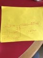
Hey! I am a mechanical engineer and I am in my final design class. Our project is to make a solar powered power system for a UAV. I have a quick question, if I want to use solar panels to slow the draw of the battery; technically, I should be able to use a few diodes to force the current together and prevent the battery current from flooding into the solar panels, right? I have a picture of how I thought the connections would be made, but I definitely do not have that much experience in diodes, please help!
 

Attachments

Dodgydave

Joined Jun 22, 2012
11,302
The diodes just prevent backwards current flow, they don't control the current or voltage into the battery, you need a Voltage regulator for that .

Here is one example ...

solar-inverter-battery-charger.jpg
 

Thread Starter

gahigg1

Joined Mar 15, 2018
8
Thank you for the response, but the question is, can I use diodes to force the current from the battery and from the solar panels to one node, which then is forces to a current sensor?
 

Dodgydave

Joined Jun 22, 2012
11,302
Yes you can use Steering diodes from each voltage source , but only one source would dominate the current drain at a time, until they all equalise in voltage .
 

ebp

Joined Feb 8, 2018
2,332
You need to provide a little more info about the battery and the photovoltaic (PV) array.

There are many "bang-bang" charge controllers available at low cost for lead-acid batteries. They connect the solar array directly to the battery until the battery voltage reaches the charged set-point voltage, then turn off to prevent overcharge and back on to continue charge.

A photovoltaic cell/module is a "soft" voltage source, so its voltage is simply pulled down to the battery voltage as long as the battery can accept charge. It behaves more or less as a current source where the current is very linearly proportional to illumination. To get decent performance from your solar array it needs to be reasonably well matched to the nominal battery voltage in terms of the maximum power point (MPP). For example, for 12 volt lead acid batteries which are around 13.8 V at full charge, an array with MPP voltage of about 15 to 16 V is typical. In general, there is nothing to be gained by using a linear regulator as opposed to a simple threshold-controlled switch. If you want to diode-OR your battery with the PV array then the downstream circuitry must be able to accept the higher voltage or you will need a regulator.

If you are using lithium batteries, things are messier if you want to have the PV array connected to the battery and the load driven from that battery.
 

wayneh

Joined Sep 9, 2010
17,498
Our project is to make a solar powered power system for a UAV.
You should keep one thing in mind - that it's not trivial to get enough power out of a solar system to make up for the extra power needed to keep it aloft. Yes, of course it can be done, but it's not easy. What's easy is to add weight that just takes more power than it gives back.

The most efficient design decision might be to leave the solar power system off altogether. That may not be an option in the context of your class.
 

Thread Starter

gahigg1

Joined Mar 15, 2018
8
We were planning on using two 14.8V 4S 3000mAh 30C LiPo batteries in parallel which would also be in parallel with a solar panel array consisting of 30 solar panels in series. Each solar panel has a voltage of 0.574V and a current of 5.83A with an efficiency of 21.8%. Our thought was that since the solar panel array will have equivalent voltage of 17.22V and 5.83A, I would implement a voltage divider to make sure 14.8V was the output voltage. Let me know your thoughts.
 

ebp

Joined Feb 8, 2018
2,332
Since the array will not be actually charging the cells, as I understand it, and a fully charged battery will be around 16.8 volts, you probably don't need to do anything other than diode-OR (schottky diodes or "ideal" diodes with FETs and a controller) the battery & PV array together. You do need to verify that the PV array won't produce more voltage than the load can handle when it is the sole supplier of the load and the load is drawing the least current it would under any circumstances. Consult the PV cell data, noting temperature effects. If you need to limit the voltage from the array, a simple shunt regulator (basically a high-power zener diode made with a zener and a bipolar transistor) is probably just as good as anything else. Be sure to consider the heat it would generate. When you've done all the arithmetic you might decide it is better to omit some cells from the array to lower the total voltage slightly. A linear regulator could be used, but it takes more parts and will always waste a little power.
 

Sensacell

Joined Jun 19, 2012
3,447
The problem with a linear regulator or voltage divider is that you end up throwing the excess power away.

You really need a switching type of regulator that EFFICIENTLY converts the solar cell voltage to a voltage very near the battery voltage.
Then OR these sources together with a diode or MOSFET.

What you don't want is the solar thingie trying to charge the battery in an uncontrolled manner.
 

Thread Starter

gahigg1

Joined Mar 15, 2018
8
Do you have any suggestions for the regulator? I actually just finished constructing the circuit in LT spice, now I need to determine how to reduce the array voltage. By the way, I also really appreciate the responses!!
 

Thread Starter

gahigg1

Joined Mar 15, 2018
8
Another question, if the combined batteries produce a current of up to 180A, what size electronic speed control would I need to hold and regulate that much current??
 

Alec_t

Joined Sep 17, 2013
14,313
if the combined batteries produce a current of up to 180A
That may be their absolute maximum allowable current, but what maximum current does the motor (or set of motors) actually need? If it's anything approaching that value then the solar array output capability of 5.8A looks woefully inadequate.
 

ebp

Joined Feb 8, 2018
2,332
I agree totally with Alec. Very high current for a motor puts a different spin on things entirely - maybe.

If the PV array power output can be gainfully used by a steady-state load, then the configuration with the battery and PV array dode-OR'd together should have some merit. If the steady state load is significantly below what the PV array can supply, then much of the array's potential is wasted and it would be preferable to connect the array to the battery. However, charging lithium cells in series demands a charge-balancing controller to prevent spontaneous disassembly of the battery pack (without balancing one cell can get overcharged, which can be catastrophic with lithium cells).

In order to make a sensible recommendation on a regulator it is necessary to evaluate where the PV array will operate on its I vs V curve and it is necessary to know if the load can be safely operated with the maximum voltage from the array without regulation. Any linear regulator will produce heat and at the differential you are using a switcher is not likely to produce enough benefit to warrant its use. Switchers must be specially designed to work properly with PV input in any case.

EDIT: I'm assuming you are talking about a hobby-type brushless motor controller. I know nothing about them.
 

Thread Starter

gahigg1

Joined Mar 15, 2018
8
If I were to connect all the solar panels in parallel, the resulting current will be very high. Is there any way to safely connect the LiPo battery and the solar panels so that they will work together and produce a higher output current to the electronic speed controller?
 

wayneh

Joined Sep 9, 2010
17,498
If I were to connect all the solar panels in parallel, the resulting current will be very high. Is there any way to safely connect the LiPo battery and the solar panels so that they will work together and produce a higher output current to the electronic speed controller?
There are several considerations. Primary is the controller itself and what it needs for optimum power efficiency. Its datasheet should give clues about this. I doubt it wants 0.5V input. It probably wants a voltage up near its maximum, whatever that is. You’ll want to arrange your cells to optimize power and that will be largely dictated by your controller and any intervening DC-DC converter in between the panel and the controller.

Another concern is how the panel reacts to some of its cells being shaded. This seriously degrades output in ‘simple’ hookups. Modern panels essentially isolate individual areas so a problem won’t bring down the entire panel. This may be beyond the scope of your project.

Back to the controller. You should be aware that there are off-the-shelf products intended to deliver power from a solar panel to a battery charger and a load. They’ve solved the various problems and do a good job with decent efficiency. You just need one sized for your panel and load wattages. I wouldn’t bother building your own unless that’s specifically assigned as part of your project. Or maybe if you need to make it lighter.
 

Thread Starter

gahigg1

Joined Mar 15, 2018
8
What is the name of the one I can buy? I was thinking about connecting only a few solar panels in series, enough that the resulting theoretical voltage was 14.37V and the current would be 5.83A. If the battery I was to use is rated 14.8V, is the solar panel power enough that I would be able to use a regulator?
 
Top