
Hi!
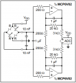
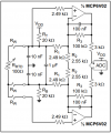
I was studying the datasheet of an Op-Amp manufactured by Microchip, MCP6V01. On page 29 of the same, there are two circuits labeled as Figure 4-16 and Figure 4-17, you may refer to the attachments for the circuits. Can anyone please explain to me the purpose of R1 and R2, labeled in Figure 4-17, and their effect on the system? Referring to Figure 4-16, R2 is still there, but R1 is not.
I am not able to figure out what purpose they serve, and how the system would be affected when they are removed, either as well as both.
Thank you.
Attachments
-
 42.7 KB Views: 17
 -
 57.4 KB Views: 18


