Trouble understanding AC motor speed regulator circuit

Thread Starter

shady_engineer

Joined May 16, 2014
1
Hey Guys

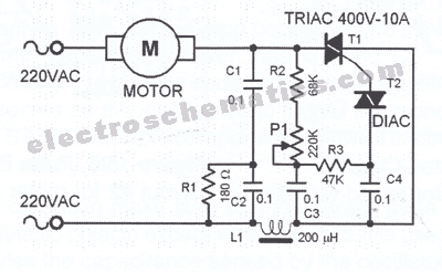
I want to build a motor speed regulator circuit and I've came across this schematic:


Before I build it I want to understand how it works in case if I wanted to customize it. Could someone help me
understand what the following parts of the circuit exactly do:


Thanks in advance to anyone who answers ;)
 

MaxHeadRoom

Joined Jul 18, 2013
28,702
They are there for (electrical) noise suppression.
Triac controllers can throw out a lot of EMI.
Incidentally the only brushed motor to use with that is a Universal type.
Max.
 

DickCappels

Joined Aug 21, 2008
10,187
The red box is a snubber to keep the voltage across the triac from changing so fast that the triac is turned on by current through the capacitance between MT2 and the gate.

Don't know why L1 (the green box) is there.

The yellow box is a two pole delay network that controls the phase in the AC half cycle at which the diac fires to turn on the triac.
 

MaxHeadRoom

Joined Jul 18, 2013
28,702
The H.D. type that I have fixed or cannibalized have the choke, it is in the form of a 1" length of ferrite with two layers of #14g enameled wire.
These are usually used for EMI suppression (high impedance to switching noise).
Max.
 
Last edited:

THE_RB

Joined Feb 11, 2008
5,438
L1 is to stop HF spike noise (from the AC mains or motor) going through C4 and turning the DIAC and TRIAC on (causing false triggering).

Ideally the DIAC should only be turned on by the slow rise of voltage each halfcycle through the RC timing networks.
 
Top