
Hi all, I realized a toggle button using ne555, so everything is ok.
Now, I'd like to add the possibility to simulate pressing over digital signal from mcu.
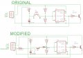
I thought to use a transistor (which should act as a switch) but it does not work, the circuit is correctly closed, but not 'clicks' as if it were closed by pressing the button.
The problem is probably due to the logic of charging and discharging of the capacitor, here the two schematic before end after changes:
http://www.flickr.com/photos/91531577@N08/8313927732/
I noted that every time I press the button, the polarity of the two ends of the button are reversed and so I added a diode to avoid that the current flow over the transistor, this system would be fine only when the polarity of the terminals A and B (indicated in the schematic) were respectively + and -, and not the opposite. I would avoid for this solution to use a relay.
I think that it is technically more interesting solve the problem by using a handful of components if possible, what do you think?
New Happy Year to all.
driver
Now, I'd like to add the possibility to simulate pressing over digital signal from mcu.
I thought to use a transistor (which should act as a switch) but it does not work, the circuit is correctly closed, but not 'clicks' as if it were closed by pressing the button.
The problem is probably due to the logic of charging and discharging of the capacitor, here the two schematic before end after changes:
http://www.flickr.com/photos/91531577@N08/8313927732/
I noted that every time I press the button, the polarity of the two ends of the button are reversed and so I added a diode to avoid that the current flow over the transistor, this system would be fine only when the polarity of the terminals A and B (indicated in the schematic) were respectively + and -, and not the opposite. I would avoid for this solution to use a relay.
I think that it is technically more interesting solve the problem by using a handful of components if possible, what do you think?
New Happy Year to all.
driver
Attachments
-
 129.1 KB Views: 58


