Thevenin Equivalent with dependent source

Thread Starter

Jess_88

Joined Apr 29, 2011
174
hey guys :)

I'm having some trouble figuring out the Thevenin equivalent for this circuit.
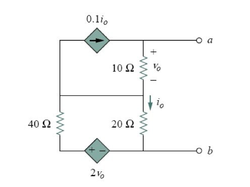


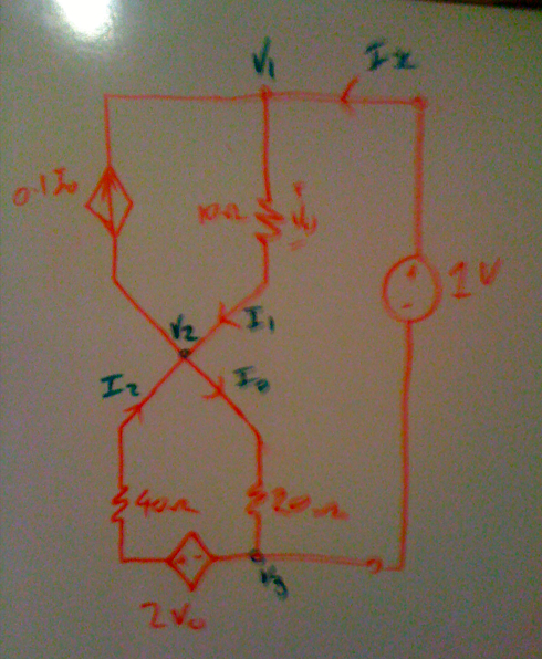
I have started trying to analyse the circuit by inserting a 1V source across the terminals "a" and "b".

With the 1 volt input across terminals "a" and "b", I have tried to determine the current entering the circuit to allow for determining the equivalent resistance of the circuit (Rth = 1V/I).

This is when I starting getting confused.
labelling the current through the 10 ohm resister i1 and the current though the 40 ohm resister i2.

Analysing the the current at the short circuit (s/c => i1 and i2 entering while 0.1Io and Io leaving), led to my understanding that-
Io + (0.1)Io = i1 + i
Io = (10/11)(i1 + i2)


I'm really not sure if my interpretation of the circuit is correct at all :( or even if I have the right approach to determining the Thevenin equivalent.


Thanks so much guys
:)
 

jegues

Joined Sep 13, 2010
733
have started trying to analyse the circuit by inserting a 1V source across the terminals "a" and "b".

With the 1 volt input across terminals "a" and "b", I have tried to determine the current entering the circuit to allow for determining the equivalent resistance of the circuit (Rth = 1V/I).

This is when I starting getting confused.
Your logic up to this point seems fine. All that's left to do now is to develop a set of equations that will allow you to solve for the current leaving the 1V source you had applied across terminals a-b.

I used mesh analysis for the job, but you can take whichever approach you prefer.

have started trying to analyse the circuit by inserting a 1V source across the terminals "a" and "b".

Analysing the the current at the short circuit
Also, there is no need to analyze anything to do with the short circuit current. If you're doing so to try to the determine the thevenin voltage, well don't bother because it is zero, you only have dependent sources.
 

Thread Starter

Jess_88

Joined Apr 29, 2011
174
thanks for the quick reply :)

I just a little confused by
"there is no need to analyze anything to do with the short circuit current"

because when I re-draw the cct-


dont I fine the current leaving the 1V source (Ix) as -
Vo = 1V = V1

I2 = 2Vo/40
= 2/40
=1/20 A

I1 = (0.1)Io + Ix = V1/10
V1 = 1V
I1 = 0.1A = (0.1)Io + Ix, (Io = (10/11)(i1 + i2))
0.1 = 0.1(10/11)(0.1 + i2) + Ix
11 = 0.1 + 1/20 + 11Ix
11Ix = 10.85
Ix = 217/220 A (0.986A ~ 1A)

... or is the just crazy talk?
 

jegues

Joined Sep 13, 2010
733
thanks for the quick reply :)

I just a little confused by
"there is no need to analyze anything to do with the short circuit current"

because when I re-draw the cct-


dont I fine the current leaving the 1V source (Ix) as -
Vo = 1V = V1

I2 = 2Vo/40
= 2/40
=1/20 A

I1 = (0.1)Io + Ix = V1/10
V1 = 1V
I1 = 0.1A = (0.1)Io + Ix, (Io = (10/11)(i1 + i2))
0.1 = 0.1(10/11)(0.1 + i2) + Ix
11 = 0.1 + 1/20 + 11Ix
11Ix = 10.85
Ix = 217/220 A (0.986A ~ 1A)

... or is the just crazy talk?
When you write equations for I2, why are you only considering the dependent voltage source?

I would argue that,

\(I2 = \frac{2V_{o} - V_{2}}{40 \Omega}\)

Anyways, try taking a more structured approach to the problem, if not you find yourself always scrambling to generate equations, and making mistakes.

You have three loops in the circuit you've drawn, one of which contains a dependent current source. From this you should be able to write 3 mesh equations. Also after doing so, you can define you dependent parameters such as Vo, io in terms of these mesh currents.

You'll have generated a system of linear equations which can be solved using basic algebra.
 

Thread Starter

Jess_88

Joined Apr 29, 2011
174
ah ok.

so, I have denoted currents in the loops 1,2,3 (from loop on top left clockwise).
I get-
0.1Io +10I1 = 0
10(I2 - I1) +20(I2 - I3) = -1
- 2Vo + 60I3

then-
Io = I3 - I2
Vo = 10(I1 - I2)

substituting in Io and Vo
10I1 - 0.1I2 + 0.1I3 = 0
-10I1 +20I2 -20I3 = -1
10I1 - 10I2 + 60I3 = 0

dose that look right to you?
I'm just a bit unsure of my Io and Vo.
 

jegues

Joined Sep 13, 2010
733
ah ok.

so, I have denoted currents in the loops 1,2,3 (from loop on top left clockwise).
I get-
0.1Io +10I1 = 0
10(I2 - I1) +20(I2 - I3) = -1
- 2Vo + 60I3

then-
Io = I3 - I2
Vo = 10(I1 - I2)

substituting in Io and Vo
10I1 - 0.1I2 + 0.1I3 = 0
-10I1 +20I2 -20I3 = -1
10I1 - 10I2 + 60I3 = 0

dose that look right to you?
I'm just a bit unsure of my Io and Vo.
I'm confused about your frist equation.

You have three mesh currents flowing clockwise around 3 meshes.

The loop at the top is mesh 1 (with I1), to the right, mesh 2 (with I2) and at the bottom mesh 3 (with I3).

By inspection I1 = 0.1io, but we don't need to make this subsitution until later on.

Generating mesh equations for the 3 loops (I'll give you the first mesh),

\(10I1 - 10I2 = 0\)

Do this for all 3 meshes, then once you've done so, start worrying about writing equations for Vo and io.
 

Thread Starter

Jess_88

Joined Apr 29, 2011
174
I see...yeah that was silly of me.

10I1 - 10I2 = 0
-10I1 + 30I2 -20I3 = -1
-20I2 + 60I3 + 10(I1 - I2) = 0

Then could I just use cramer's rule to fined I3 which is the current from the source?
 

jegues

Joined Sep 13, 2010
733
I see...yeah that was silly of me.

10I1 - 10I2 = 0
-10I1 + 30I2 -20I3 = -1
-20I2 + 60I3 + 10(I1 - I2) = 0

Then could I just use cramer's rule to fined I3 which is the current from the source?
Your equations look good expect for the last one.

Vo = (I1-I2)10

So, 2Vo = 20(I1-I2)

Since you are looping in a clockwise fashion,

-20I2 + 60I3 - 20(I1-I2) = 0

Now you can simply solve the system of equations for I3, but be careful.

We defined I3 in a clockwise fashion. When we wire in this 1V source we want the current that the source is supplying to our circuit, so the current we are interested in is infact -I3.
 

Thread Starter

Jess_88

Joined Apr 29, 2011
174
hi again.
just a couple of small questions for this.

so solving the equations I get I3 = 1A
but as jegues noted earlier, I want -I3.
so Rth = 1V/-1A
but how can you have a negative resistance?

I'm also just a lil puzzled bout the original question for the circuit " fined the thevenin equivalent of the cct"
Is that just asking my Rth?... because it contains no independent sources
 

t_n_k

Joined Mar 6, 2009
5,455
As a check for your results...

Another approach I used was to assume a current of 1A is flowing in the 10Ω resistor - then deduce the voltage Vab required to achieve this.

Vo=V10Ω=10V

2*Vo=20V [Which is the controlled voltage source output]

The current from Vab would be (1-0.1*Io).

The current flow out of the controlled voltage source would be

Io-(1-0.1*Io) or 1.1*Io-1.

But 20V=40*{1.1*Io-1}+20*Io

Giving 64*Io=60

or Io=0.9375A

For which Vab=10+20*0.9375=28.75V

The resistance looking into terminals ab would therefore be

Vab/(1-0.1*Io)=31.724Ω
 
Last edited:

Thread Starter

Jess_88

Joined Apr 29, 2011
174
I'm a little bit confused with some of the equations you made.

1) how can you assume 1A flowing throw the 10 ohm resistor?
wouldn't it be - 1A + 0.1Io???

unless instead your using a current supply input to the circuit to analyse the voltage at the output???

2) Vab = 1 - 0.1Io
is that the current leaving the negative terminal of the voltage supply???

did you made the equations using the 1V input or is it o/c from a-b?

it would be great if you could explain how you got some of your equations.
I just don't understand how you did them.

thanks a heap :)
 

jegues

Joined Sep 13, 2010
733
so solving the equations I get I3 = 1A
but as jegues noted earlier, I want -I3.
so Rth = 1V/-1A
but how can you have a negative resistance?
It is the case in some of these thevenin problems whereas the result is a negative resistance, although in this case that is not the case.

The resistance looking into terminals ab would therefore be

Vab/(1-0.1*Io)=31.724Ω
I had solved the problem with the equations I have provided you with and obtained the same answer as tnk, so you must have made a mistake solving for the currents.

tnk has also offered an alternate solution for you to study.
 

Thread Starter

Jess_88

Joined Apr 29, 2011
174
so I have
10(I1 - I2) = 0
10(I2 - I1) + 20(I2 - I3) = -1
20(I3 - I2) + 40I3 - 2vo = 0

forming the matrix (A)
[10,-10,0] [I1] = [0]
[-10,30,-20] |I2| = [-1]
[-20,0,60] [I3] = [0]

det(A) = 8000 = delta

Matrix(B) for I2
[10,0,0]
[-10,-1,-20]
[-20,0,60]

det(B) = -600

I3 = delta (B)/delya
= -600/8000
=-0.075

this is what I have so far
is this correct at all???

now, I dont know how to relate I3 to the what you said to what you were saying earlier.

but couldnt I just use another matrix to find I1?
and wouldnt I1 = the current supplied by the 1v source?
 

jegues

Joined Sep 13, 2010
733
so I have
10(I1 - I2) = 0
10(I2 - I1) + 20(I2 - I3) = -1
20(I3 - I2) + 40I3 - 2vo = 0

forming the matrix (A)
[10,-10,0] [I1] = [0]
[-10,30,-20] |I2| = [-1]
[-20,0,60] [I3] = [0]
The problem is with your first equation.

\(I_{1} = 0.1i_{o}\)

\(i_{o} = I_{3} - I_{2}\)

\(\Rightarrow I_{1} + 0.1I_{2} - 0.1I_{3} = 0\)
 

t_n_k

Joined Mar 6, 2009
5,455
I'm a little bit confused with some of the equations you made.

it would be great if you could explain how you got some of your equations.
I just don't understand how you did them.

thanks a heap :)
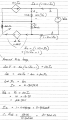
I've attached an image of a more detailed solution.

The idea was to force the current in the 10Ω to be 1A, based on an as yet unknown voltage source connected across terminals a & b. Not the 1V source you assumed.

The current from the applied source would have to be (1-0.1*Io) to satisfy Kirchoff's Current Law at the top node with the current directions indicated.

I was really only flagging this solution as a means to indicating the correct answer without actually spelling out the solution using your adopted approach.

Congrats on getting the solution.
 

Attachments

Top