The general idea of my project is to create a circuit which reads the temperature from a NTC sensor and displays it on the computer screen. I created a thread a few months back as I needed help to start my thermistor project (https://forum.allaboutcircuits.com/...ridge-instrumentation-amplifier-stuck.158439/). I am now stuck as I have no idea how to progress, so here's where I'm at:
Besides that, I also have no idea how to connect all of this to a multiplexer as I'm required to do in order to manually (????) switch between the 2 signal conditioning circuits. AFTER THAT I'm even more confused as I have no idea how to connect all of this to my arduino / arduino's ad converter (even though that's the least as I have made lots of research on that topic and I am used to code arduinos in other subjects).
I am sorry if something is hard to understand but I'm up to explain things better in order to learn and get the best out of this project on my evaluation day.
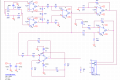
- As you can see from picture nº1, I've successfully built a Wheatstone Bridge + Instrumentation Amp. circuit and the outputs are correct (for a 55ºC - 150ºC temperature gap, I successfully achieve the [0 ... 5]V gap required).
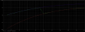
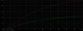
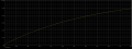
- Picture nº2 shows both the Bridge and the I.A. output voltages depending on the current temperature, everything fine!
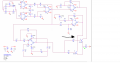
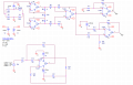
- I then proceeded to build 2 signal conditioning circuits (as shown in picture nº3) as I was required to break my I.A. output in 2 parts (this was made so that 1 part would be more accurate (55ºC - 95ºC to a [0...5]V gap) than the other (95ºC - 150ºC to a [0...5]V gap). My commutation point is 95ºC, 3.25V ).
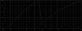
- Picture nº4/5 shows both outputs according to their respective temperature gaps. As you can see, the graph in picture 4 is way more linear than the other, making it easier to read small temperature changes.
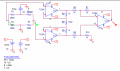
- Given that I'm choosing one of the two signal conditioning circuits, I had to build a non-inverting voltage comparator with hysteresis (picture nº6) in order to compare my commutation point voltage (3.25V) with another voltage (after following my teacher's explanation + calcs, I figured out that the other voltage was 3.25V ± 55mV). Can attach my calcs later if needed.
Besides that, I also have no idea how to connect all of this to a multiplexer as I'm required to do in order to manually (????) switch between the 2 signal conditioning circuits. AFTER THAT I'm even more confused as I have no idea how to connect all of this to my arduino / arduino's ad converter (even though that's the least as I have made lots of research on that topic and I am used to code arduinos in other subjects).
I am sorry if something is hard to understand but I'm up to explain things better in order to learn and get the best out of this project on my evaluation day.
Attachments
-
 13.6 KB Views: 19
 -
 145.4 KB Views: 14
 -
 21.4 KB Views: 13
 -
 139.7 KB Views: 12
 -
 145.7 KB Views: 12
 -
 31.3 KB Views: 14