Happened across this E-book page:
http://www.allaboutcircuits.com/vol_3/chpt_4/2.html
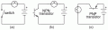
The first Figure (c) is incorrect. The PNP transistor will act as a voltage follower (common collector) rather than a switch. The load (lamp) needs to be between the source negative side and the transistor's collector.
Re-use of figure letters on the same page is not a good idea, as it can lead to confusion.
The 2nd figure (a) and (b) are not correct. The transistor will not saturate; Vce will not go below around 0.63v, or the Vf of the BE junction.
http://www.allaboutcircuits.com/vol_3/chpt_4/2.html
The first Figure (c) is incorrect. The PNP transistor will act as a voltage follower (common collector) rather than a switch. The load (lamp) needs to be between the source negative side and the transistor's collector.
Re-use of figure letters on the same page is not a good idea, as it can lead to confusion.
The 2nd figure (a) and (b) are not correct. The transistor will not saturate; Vce will not go below around 0.63v, or the Vf of the BE junction.