Tesla's Egg of Columbus

shortbus

Joined Sep 30, 2009
10,045
Munk - to do it with DC, it could be done with a stepper motor driver. A unipolar stepper driver IC is fairly cheap. You would decide the current/amperage you want to use and check one of the 'wire amperage' charts to find out the length you need for that number of amps.

Then make a toroidal ring out of either steel banding(like they use to strap stuff to a skid) or even heavy steel wire, like fence wire. Wrap the ring with electrical tape. Then wind the wire on the ring in four separate coils, covering the ring. Wrap with electrical tape again.

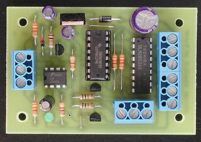
Then make a 555 timer circuit to control the step input of the stepper IC. wire the coils to the stepper IC and power it up.

That's basically what the guy in this video is doing; http://www.youtube.com/watch?v=EPZRXFPU4Mw&NR=1&feature=fvwp
In the lower left corner you can see his controller, looks like he's using three coil pairs instead of two, because of the way he has the coils made. He has them on end pointing at the egg instead of a toroidal coil. That points the magnetic field at the egg instead of covering a larger area like Tesla did. His egg doesn't move as good as the ones using a toroid.

Thatoneguy - most BLDC motor drivers are expecting three Hall effect signals from the inside of the motor to work. Thats why I am suggesting a stepper driver instead of a BLDC driver, to make this simpler.
 

Thread Starter

Munk

Joined Jan 2, 2011
36
@thatoneguy

I don't have any experience soldering or reading schematics, however I did take a look at the unipolar stepper motor driver and -- I think -- I understand. (see below and tell me if I'm right lol). As far as 'pointing each core inward' does that mean I have to reverse the wiring or something, or do you mean physically turning each pole inward (not sure how to do this without taking a hacksaw to the stator and trying to Frankenstein it back together inside-out.) To make matters worse, I have no idea what a logic inverter is nor a MOSFET (even after googling them). :(

@shortbus

Here is what I found after searching for a unipolar stepper motor driver. By looking at the actual board, and comparing that to the schematic, I think I recognize what's what (though I don't feel i've wrapped my head around how it actually works...but maybe that's not necessary). The + in the upper right hand corner is the positive electrical connection, and the - is the negative connection. The little black box on the far left-hand side in the center is that 555 timer you were talking about (which would need to be the right value to get the frequency I need, i.e 35-40Hz?). The (2 phase) motor coils would be connected to the 2nd, 3rd, 4th, and 5th screws on the blue box on the right side (since positive would connect to the first, and negative to the last screw). The two black boxes in the middle (IC2 and IC3) create the "phases" we would need.

This specific motor stepper is 1 amp, and based here I could use a 12V power supply and up to 30 feet of 22g wiring and only loose 1 volt. I am not sure if that'll do the trick...but I assume the more volts I push through, the stronger the field. Is that right?


Last edited:

thatoneguy

Joined Feb 19, 2009
6,359
I think the stepper motor driver is the simplest and cheapest solution for the multiple phases yet. Sorry I didn't think of it.

When I mentioned "orient the coils inward", it was basically saying "cut the coils apart, physically point them in a new direction, glue together". The toroidal solution that shortbus mentioned above may be simpler, toroids of that size are fairly easy to wind since you can slip the whole spool of wire in and around it. Plus, there's a satisfaction of winding your own coil over purchasing, there's a bit of Zen about it. The MIT egg video showed the various poles color coded by the coating if you look at it again.

For the 1A Stepper driver, running at 12V, you'd need to wind at least 12Ω worth of wire around the toroidal core per coil to keep the current levels under 1A.

What diameter platform were you looking at building? That, along with voltage/current, is what will decide the size of the toroid.
 

Thread Starter

Munk

Joined Jan 2, 2011
36
I am not sure what size is needed to keep the object "in" the magnetic field, but the object is no larger than 1.25" in any direction. With that being said, I suppose I could go as small as a 4" toroidal coil (outer diameter) but I would like to use a T650 if possible (6.5 inches). For voltage, I really have no point of reference to know how much I need, so I guess 12V is a good place to start (hopefully it'll spin a 30 gram piece of magnetic stainless steel)

Is there any advantage to using AC over DC in this sort of application, or vice versa? Either way it'll be connecting to the AC outlet, and so will need a transformer or step down.
 
Last edited:

thatoneguy

Joined Feb 19, 2009
6,359
Both are "AC", one is just line frequency sinewave, while the stepper motor produced 3 phase square wave output. Both are AC of sorts. I guess you are thinking "Line Powered" when you refer to powering it from a step down transformer, and the fact the driver starts with DC, but produces the squarewave AC.

Hope that clears up a bit of confusion.

The toroid size of 6-8" should be fine, just be sure to get enough windings on each pole and insulate well.
 

shortbus

Joined Sep 30, 2009
10,045
Use a power supply from a computer to power this. A computer supply will give you both 12VDC and 5VDC and will give you isolation from the mains in one simple package. And if you have a old PC it will be cheaper than a transformer and the other parts(bridge rectifier, supply capacitor, etc.) Even a new PC power supply would be cheaper.
 

shortbus

Joined Sep 30, 2009
10,045
Munk - Here is a link to a kit for a unipolar stepper driver; http://www.electronics123.com/s.nl/it.A/id.396/.f This is the cheapest one I could find online, and just happens to be a local to me store that I've dealt with. This is a kit that includes everything, no board for you to worry about. Just put in the parts and solder. It even has the timing/step control built in.
 

Thread Starter

Munk

Joined Jan 2, 2011
36
This looks like it's exactly what I need, and can even support up to 35V and 6A to the motor itself, need be. Not too shabby. Now, since this is used for a 5, 6, or 8 wire stepper motor, that means that I would need 5, 6, or 8 separate windings on the toroid, each individually connecting to the driver, correct? Also, how does one tune the frequency on this device using the built in controls? Is there a knob or switch somewhere on it?

The toroid I am thinking about getting is 5.2" outer diameter, 3" inner diameter, and .8" thickness. What is the "AL nH/Sq.N" or the "U=" mean? For example, is it better to have a AL nH/Sq.N of 149 or 45? Is it better to have a U of 75 or 22?
 

shortbus

Joined Sep 30, 2009
10,045
This looks like it's exactly what I need, and can even support up to 35V and 6A to the motor itself, need be. Not too shabby. Now, since this is used for a 5, 6, or 8 wire stepper motor, that means that I would need 5, 6, or 8 separate windings on the toroid, each individually connecting to the driver, correct? Also, how does one tune the frequency on this device using the built in controls? Is there a knob or switch somewhere on it?
The part about the 5,6,8 wire motors doesn't apply to what your trying to do. That just means when using it for a step motor it only works for a unipolar motor. There are two basic types of stepper motors unipolar and bipolar, it has to do with how the motor is made internally. Each takes a different driver. Worrying about this for your project will just over complicate and go off topic. If you want to learn about it after this project is working, people here will help.

The frequency is changed by VR1 in the schematic. Link to schematic;

http://www.electronics123.net/amazon/datasheet/k179.pdf

If I was doing this instead of the potentiometer(VR1) on the board,it can be wired with jumper wires to a pot off the board. I assume you will make a small box of some kind to put the coils on and hide the electronic parts?
 

Thread Starter

Munk

Joined Jan 2, 2011
36
Yes, the various components will be concealed within a box. With that last post by bertus, is there something else I would need to make this thing work right?
 

shortbus

Joined Sep 30, 2009
10,045
Yes, the various components will be concealed within a box. With that last post by bertus, is there something else I would need to make this thing work right?
No, Bertus and Cdrive were referring to the schematic that you posted , not the one I linked to. Although it will need some diodes from the coil leads to ground. But you have to know how many amps the coils will draw to chose them, no big deal.
 
Last edited:

Thread Starter

Munk

Joined Jan 2, 2011
36
That's a relief...because I already bought that driver you linked :p

Ok now for the toroidal core: What is the "AL nH/Sq.N" or the "U=" mean in the specs of the toroid? For example, is it better to have a AL nH/Sq.N of 149 or 45? Is it better to have a U of 75 or 22?

http://www.cwsbytemark.com/index.php?main_page=index&cPath=206_217

EDIT: Ok, U is the permeability, and the higher the perm the better the magnetism so I want the most U I can get. I still don't know what the other value is. Anywho, isn't the amperage determined by the wire I decide to use? I suppose the idea is to get as many amps as I can manage (to get the strongest field)?
 
Last edited:

shortbus

Joined Sep 30, 2009
10,045
Munk - back in post #41 I talked about using metal strapping to make your core. The ferrite/powdered metal cores are something you don't need really. They are mainly used to make transformers and inductors, where the qualities are real important. Your project doesn't need that much quality or expense.

I don't know where you live, but, if your in the USA and near a fair sized city, look for a trucking terminal. The ones for 18 wheeler over the road semi's. Go in and ask if they use steel strapping. Tell them what your doing and ask if they will sell you some strapping. It's usually 1/2" to 3/4" wide and brownish colored. They will probably give it to you.

To figure out how long a piece you need - Take a tape measure and measure the length around something of the diameter you want your ring to be. The strapping is usually about 1/32" thick, so if you want the ring to be 1/2" thick, multiply the diameter length by 16 to give you the total length you need. If you did the measurement in inches(") divide by 12, to give you the feet of strapping to buy.

Example: 6" ring x 1/2 " thick. 6 "diameter = 18 7/8" round up to 19"
19" x 16 = 304" 304" / 12" = 25' 4" round up to 26 feet.

I don't know your age so I hope you don't think I'm talking down to you. Just trying to help, and make this as painless as possible. I wouldn't order the wire yet. We'll figure that out after the core is made.
 

SgtWookie

Joined Jul 17, 2007
22,230
Frankly, I'm wondering why Tesla used a toroidal inductor to begin with, as most of the field would remain in the core; just a small fraction of the power would be available to spin the "egg."

I'm thinking that the original was actually a transformer built with the intent of powering something else, and someone noticed or figured out that there was enough EMF available to move a small metal object.
 

shortbus

Joined Sep 30, 2009
10,045
Frankly, I'm wondering why Tesla used a toroidal inductor to begin with, as most of the field would remain in the core; just a small fraction of the power would be available to spin the "egg."

I'm thinking that the original was actually a transformer built with the intent of powering something else, and someone noticed or figured out that there was enough EMF available to move a small metal object.
SgtWookie - this was part of his experimenting on the induction motor. I think this is where he came up with the 'squirrel cage' part of the motor.The original egg itself was of copper and non-magnetic. guys making them today are really "cheating" using a magnetic egg.

I understand what your saying about the toroidal magnetic flux, but it also spreads the flux over a large area of the ring. As the development went on they learned to wind the coils in the slot-type stator in use today.
 

Thread Starter

Munk

Joined Jan 2, 2011
36
I have done some research on this steel strapping, and for a 5.2" core that is 1" thick, we are looking at about 50ft of strapping. The going rate for that amount of strapping is $35-$70, however I can get a iron powder toroid of the same dimensions for about $20. Granted, I may be able to find a place that will give me this this strapping for free locally, factoring in time, gas, etc...it seems like it would be better just to buy the toroid.

Now, I assume you can also connect a stator to this device and have it work, assuming that we wire each pole or phase separately to the driver (tried to find ones that were turned inward)?

Example 1
Example 2
Example 3
 
Last edited:

shortbus

Joined Sep 30, 2009
10,045
Munk - the stators are three phase and the driver kit is two phase.

The toroid core is made from a material that is magnetic, but because it is made of small (under .001" dia.) particles it doesn't radiate magnetic flux when wrapped with wire. This is great for the uses it was developed for, but not for what your trying to do. Powdered metal toroid cores are also made for higher frequency's than what you want.

The strapping doesn't have to be in one long piece, it can be in shorter lengths. This might be an alternative for you; http://www.homedepot.com/h_d1/N-5yc...splay?langId=-1&storeId=10051&catalogId=10053
 
Thread starter Similar threads Forum Replies Date
DerStrom8 Off-Topic 12
J General Electronics Chat 19
Top