Tank Circuit (TA2003 chip)

Thread Starter

Masood786

Joined Dec 16, 2010
11
Dear All

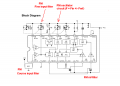
I have connected the tank circuit as shown in the data sheet of TA2003 Fm/Am radio chip for FM band. one end of the circuit goes to vcc, despite all the connections(Fm mode connections ,etc), i am unable to find any oscillations in the tank circuit, i have attached oscilloscope to Pin 13 (Oscillator input). I want to check if correct frequency goes to LO for mixing with the RF signal ( L(coil) is 6 turns and C is 4-50 pf for fm band)

Masood
 

Audioguru

Joined Dec 20, 2007
11,248
The capacitance of the probe of your oscilloscope will kill the oscillations of a radio's 107MHz oscillator.
At 107MHz, only 10pf has a reactance of only 150 ohms.

The input capacitance of your 'scope probe might be 20pf then its reactance is only 75 ohms which is like a dead short.
 

Thread Starter

Masood786

Joined Dec 16, 2010
11
Thanks Audioguru & Bertus

i have connected the transistor as shown in the data sheet "Test Circuit 2" and then connected it to scope but no luck. one thing i have not done is bypass capacitors, but i don't think it would make any difference.
 

Thread Starter

Masood786

Joined Dec 16, 2010
11
Dear Bertus

you have been very helpful in clearing my Rf concepts. i have one confusion regarding OSC coils and tuner coils.

1. If in tank circuit inductor (hand made or purchased from market) is connected to the oscillator input of chip then is it called oscillator coil or is it called by any other name xx coil ?

2. Is there any characteristic that separate tuning coil from osc coil?

3. Is tuning coil a pick up coil that acts as antenna and osc coil does not pick signals but provide required resonance?

4. can i use tune-able/plastic moulded inductor(i don't know it's osc coil or else) either in tank circuit for oscillator input and also in Rf front end for tuning purpose.
Can same coil be used for different tasks

Masood
 

Thread Starter

Masood786

Joined Dec 16, 2010
11
Can any one tell me clearly regarding OSC coils and tuner coils.

1. If in tank circuit inductor (hand made or purchased from market) is connected to the oscillator input of chip then is it called oscillator coil or is it called by any other name xx coil ?

2. Is there any characteristic that separate tuning coil from osc coil?

3. Is tuning coil a pick up coil that acts as antenna and osc coil does not pick signals but provide required resonance?

4. can i use tune-able/plastic moulded inductor(i don't know it's osc coil or else) either in tank circuit for oscillator input and also in Rf front end for tuning purpose.
Can same coil be used for different tasks

I am not able to successfully build FM radio using TA2003. I think i am not able to drive TA2003 FM OSC.

Masood
 

Audioguru

Joined Dec 20, 2007
11,248
It is a cheap radio because its FM input does not tune the frequency, it tunes only the entire frequency band. Also, both inputs do not have AGC. Therefore the inputs are easily overloaded by strong local stations.
My Sony Walkman radio is similar except is stereo for FM. It has an FM local-distant attenuator switch to avoid overloading. In the city it must be set to local and then it cannot pickup distant stations.
 

Thread Starter

Masood786

Joined Dec 16, 2010
11
Hi All,
I have connected all the components for TA2003 FM mode but it seems that i am unable to tune any station(FM band coil and gang capacitor). I have connected all components over breadboard (TA2003 and all required Rs & Cs) except tank circuit which is soldered in separate wire-board, i thought that tank is most sensitive part so i put that on separate wire-board but still unable to Pick any station. Any ideas what has gone wrong? has any one used this chip over breadboard? (can we use our design for 88-108 mhz over breadboard)

Masood
 

bertus

Joined Apr 5, 2008
22,277
Hello,

The breadboard could be the problem.
The metal contact strips in a breadbooard make capacitors between the pins of the IC.
For audio frequencies is this no problem, but for RF this will be a great problem.

Look at the construction of a breadboard in the attached PDF.
I also attached a PDF on RF prototyping.

Bertus
 

Attachments

Audioguru

Joined Dec 20, 2007
11,248
A breadboad is used for DC and some audio circuits. Its capacitance and inductance is far too high for a 100MHz FM radio circuit.
Use a compact pcb.
 
Top