
Hi everyone!
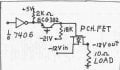
I am working on a circuit that has a dual power supply (+/- 12V),
with an additional +5V TTL supply, and I need to
be able to switch the negative voltage (Vout) by a logic level voltage
Vin such that Vin=0V should give Vout=0V and Vin=+5V should give Vout=-12V. I have a power NPN between ground and -12V, but now I need "something" to hook up to the base of this transistor that takes the logic levels mentioned as inputs.
The job would probably be simply done with an op-amp, but since I
will need a large number of these switch stages, I would like to avoid
that if possible. So I'm looking to see if anyone can think of a nice,
simple solution without ICs. I have a feeling that the answer might be
a FET, but I can't seem to get that to work.
Any help deeply appreciated!
")


