Suggestions for very fast control of highly transient load

Thread Starter

SiCEngineer

Joined May 22, 2019
442
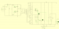
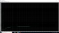
I have a converter whose output must be pulsed at anywhere from 1Hz to 100kHz at duty cycles of 5% to 95%. Using standard voltage mode control, I am able to regulate the output up to ~70% duty cycle for frequencies up to approximately 50kHz. 100kHz operation at low duty cycles such as 5% is also very good. However, when the duty cycle increases to levels such as 0.95D, (especially at high frequencies), the controller does not have sufficient time to recharge the capacitors before the next transient event occurs, and therefore the voltage will decay towards zero slowly. I believe this is due to the slow nature of the voltage loop.

Does anyone have suggestions for control schemes which can act upon transient behaviour such as the above. I have also tried implementing a peak current mode inner loop and voltage mode outer loop, to no avail. I have not yet tried average current mode but I doubt it is much better. I had seen a suggestion to use digital control, with a PI controller for the current inner loop and a "PR" controller for the voltage outer loop.

Any other suggestions?
 

MisterBill2

Joined Jan 23, 2018
18,463
With only the very limited amount of information provided, I am going to suggest that a separate control stage after the converter will allow the control of the output over the whole range, since it could be buffered to prevent the control stage from affecting the converter operation.
Certainly this will add a fair amount of complexity, and so if the circuit is for a typical consumer grade product it will not be accepted. But if this is for a system where performance is more important than absolute minimum cost it should provide the control range that you seek.
 

Thread Starter

SiCEngineer

Joined May 22, 2019
442
Thank you very much for your reply Bill. First of all, is there anything else I could provide that may better improve the response you can give? Is what you refer to, "post-regulation", where there is some kind of linear regulator on the secondary side of the converter which is in addition to the usual voltage control loop? The converter is certainly not for consumer grade, and cost being minimum is not important. Performance is everything! :)
 

MisterBill2

Joined Jan 23, 2018
18,463
OK, it is a bit clearer what you are seeking, and it seems that having the converter supply voltage to an adequate capacitor group, with the converter holding that voltage steady enough so that a switching circuit can provide the on/off pulsing that whatever you are powering can perform as required. That switching will probably require the use of a fast mosfet switching transistor, or transistors, depending on the actual load current. If the load is capacitive or inductive then the switching will be a bit more complicated, probably.
It does sound like an interesting project.
 

MisterBill2

Joined Jan 23, 2018
18,463
Switching is "linear" if you look at it fast enough. So the whole question now is based on the required rise and fall times. And we have not been given much in the realm of specifications as to how fast is "fast." One millisecond rise time or one nanosecond rise time. No clue as to how to do that nanosecond rise time, though.
 

Thread Starter

SiCEngineer

Joined May 22, 2019
442
I have not yet investigated the use of a high speed linear stage at the output of my converter. My converter has two outputs, one at 600W and one at 60W. Ripple and regulation is most important on the 60W output, so a linear regulator could be good. Do you happen to have a suggestion for such a circuit that could be used for a pulsed output such as mine?

Regarding rise and fall times, the maximum duty cycle of the output load pulse is 100kHz, and the minimum is around 100Hz. Duty cycle of the pulse can be anywhere from 5% to 95% depending on the application.

I find that at the moment, especially at high frequency/high duty cycle, the PI voltage controller is simply too slow to return to the required reference voltage.
 

crutschow

Joined Mar 14, 2008
34,412
Regarding rise and fall times, the maximum duty cycle of the output load pulse is 100kHz, and the minimum is around 100Hz. Duty cycle of the pulse can be anywhere from 5% to 95% depending on the application.
Which says nothing about the required rise and fall times.

What is the voltage value you want to switch.
 

MisterBill2

Joined Jan 23, 2018
18,463
Variable frequency variable pulse rate switching of a 6000 volt DC power source is quite a "big deal". But with only 60 watts the current maximum can only be 10 milliamps, and this raises other questions. Is the load capacitive, because charging any capacitance to 6000 volts is going to draw a bit of current. In addition, achieving much capacitance in the storage capacitor is going to be both large and expensive. And you certainly will need to have a large capacitance to achieve anything like good regulation, because that 60 watt source is only able to deliver 10 milliamps .
So now will be a good time to let us know more of just what it is that you need to achieve.
And still we have no statement of the required rise and fall times of this voltage pulse. That will make a very large difference in almost every portion of the hardware, and even of the ability of that device to supply enough power.
 

Thread Starter

SiCEngineer

Joined May 22, 2019
442
Variable frequency variable pulse rate switching of a 6000 volt DC power source is quite a "big deal". But with only 60 watts the current maximum can only be 10 milliamps, and this raises other questions. Is the load capacitive, because charging any capacitance to 6000 volts is going to draw a bit of current. In addition, achieving much capacitance in the storage capacitor is going to be both large and expensive. And you certainly will need to have a large capacitance to achieve anything like good regulation, because that 60 watt source is only able to deliver 10 milliamps .
So now will be a good time to let us know more of just what it is that you need to achieve.
And still we have no statement of the required rise and fall times of this voltage pulse. That will make a very large difference in almost every portion of the hardware, and even of the ability of that device to supply enough power.
As far as I know, the load is resistive and not capacative. I have been told to model the load with a resistor. The application is for a travelling wave tube. I agree, the storage capacitors for this type of power supply is always big, and considering the solution is minimize the size of these capacitors. I don't think the switching regulation alone is enough to provide the performance required. Unfortunately I do not know about the rise and fall times, but I will be able to find out very soon and will update accordingly.
 

Thread Starter

SiCEngineer

Joined May 22, 2019
442
Can you use a high speed linear stage on the output to provide the desired pulsing?
Could you please clarify your point, I am interested to hear about this. I am unsure if I am confused - the pulsing on the output is provided by an external signal which turns the load ON or OFF. Do you mean that the linear regulator is OFF when the load is OFF and ON when the load is ON... or something like this? Could you provide an external source for something similar, or an example circuit that I could possibly simulate?
 

MisterBill2

Joined Jan 23, 2018
18,463
Depending on the requirements and how tight the regulation has to be, just having an adequately sized power supply might be enough. Some switch-mode regulators are really fast, of course "really fast" is totally trlative to what the application requires.
But most applications of high powered amplifiers vary the input signal rather than varying the amplifier, so that part is a big puzzle. Those radar sets with the megawatt pulses are possibly different, I am not familiar with how those work. The ones that I can recall all used a pulsed magnetron tube, and they just switched the power to that with a power tube. But it was the power oscillator, not an amplifier.
 

ronsimpson

Joined Oct 7, 2019
3,037
My converter has two outputs
I do not know what your supply looks like. (helpful) It is common for the power supply to only regulate one output.

The voltage on the 60W output is 6kV
6kv Ok now I know that. If your error amplifier works to 50khz then the ripple voltage (regulation) above that is only a function of the output filter capacitors.

Do you have a schematic of the power supply.

Several of us have designed TV sets and monitors where the high voltage is well regulated. The ripple / regulation on a CRT monitor is much like what you describe. On some monitors we just added more capacitors.

Can you see the load? Do you know when the load is being applied?
 

Thread Starter

SiCEngineer

Joined May 22, 2019
442
I do not know what your supply looks like. (helpful) It is common for the power supply to only regulate one output.


6kv Ok now I know that. If your error amplifier works to 50khz then the ripple voltage (regulation) above that is only a function of the output filter capacitors.

Do you have a schematic of the power supply.

Several of us have designed TV sets and monitors where the high voltage is well regulated. The ripple / regulation on a CRT monitor is much like what you describe. On some monitors we just added more capacitors.

Can you see the load? Do you know when the load is being applied?
Find attached schematic to this reply. I have not included the control but it is just a very simple PI voltage mode controller, which for some values of D and frequency of pulsing works very well. Idea is that the buck converter regulates the output voltage to the LCC bridge. At the extremes of the pulsing the output voltage either increases or decreases indefinitely as the controller is too slow to bring it back to the required set-point before the next pulse. Only one output is needed regulated, which is the 6kV, the other is not as crucial. I'm not sure what you mean about whether I can see the load. However, yes, there is a signal that comes into the power supply which is a pulse waveform which triggers ON or OFF the load, therefore it can be used within control.
 

Attachments

MisterBill2

Joined Jan 23, 2018
18,463
OK, Now I see the circuit and it looks like the high voltage switching is part of the circuit already, The capacitance to support the delivery of power will need to be where the capacitor to the right of R10 is in the circuit drawing shown.
I wonder just what you are using for a switch in that circuit.
The use of four voltage doublers in series is a bit similar to what I saw published in QST magazine a while back. It makes a lot of sense and really is a good choice for high voltage supply work. So it is a quite good design, although there are several elements that are rather undefined. Or is that where you are in the design process?
 

Thread Starter

SiCEngineer

Joined May 22, 2019
442
OK, Now I see the circuit and it looks like the high voltage switching is part of the circuit already, The capacitance to support the delivery of power will need to be where the capacitor to the right of R10 is in the circuit drawing shown.
I wonder just what you are using for a switch in that circuit.
The use of four voltage doublers in series is a bit similar to what I saw published in QST magazine a while back. It makes a lot of sense and really is a good choice for high voltage supply work. So it is a quite good design, although there are several elements that are rather undefined. Or is that where you are in the design process?
That capacitance to the right of R10 is only a small, filter capacitor of nF range. Could I add a larger one in parallel with it for that purpose?

For the inverter (Buck, HB) the switches are MOSFETs. The switches at the load side, which toggle between high and no load, are ideal switches that are included in the PLECS blockset. Unlike in LTSpice I cannot use a pulsed current source to define this. But since I was looking at a control option I thought modelling in PLECS would be better, for now. I am still in the design process and some things are still undefined. Mostly, with the control considering the highly transient load behaviour. For some load conditions the control is fine. At others, (extreme low or high duty) the output voltage rises or falls indefinitely as the control is too slow. I am not experienced in hybrid power supplies as I have not much knowledge on linear regulators and how they can be used here.

Note: Could you link me to your work in the QST magazine? :)
 

MisterBill2

Joined Jan 23, 2018
18,463
That capacitance to the right of R10 is only a small, filter capacitor of nF range. Could I add a larger one in parallel with it for that purpose?

For the inverter (Buck, HB) the switches are MOSFETs. The switches at the load side, which toggle between high and no load, are ideal switches that are included in the PLECS blockset. Unlike in LTSpice I cannot use a pulsed current source to define this. But since I was looking at a control option I thought modelling in PLECS would be better, for now. I am still in the design process and some things are still undefined. Mostly, with the control considering the highly transient load behaviour. For some load conditions the control is fine. At others, (extreme low or high duty) the output voltage rises or falls indefinitely as the control is too slow. I am not experienced in hybrid power supplies as I have not much knowledge on linear regulators and how they can be used here.

Note: Could you link me to your work in the QST magazine? :)
The article in QST was not my work, it was an article that I saw a while back. The author made one very useful observation, which was that the transformer needed many more lamenations then what the standard design thinking called for. And that supply was not actively regulated, it was instead designed for better magnetic coupling. Making the source impedance lower improves the output stability.
And if the power supply voltage falls steadily at a higher duty cycle then it is likely that the supply is not able to support that much load current and so there would need to be an adjustment to the capability of the supply.
 

Thread Starter

SiCEngineer

Joined May 22, 2019
442
The article in QST was not my work, it was an article that I saw a while back. The author made one very useful observation, which was that the transformer needed many more lamenations then what the standard design thinking called for. And that supply was not actively regulated, it was instead designed for better magnetic coupling. Making the source impedance lower improves the output stability.
And if the power supply voltage falls steadily at a higher duty cycle then it is likely that the supply is not able to support that much load current and so there would need to be an adjustment to the capability of the supply.
Okay, so the reason the voltage falls steadily at high duty cycle is because the design isn't optimized. How could that be dealt with? Increasing the number of turns on the secondary?

I tried to replace the buck converter with a buck/boost so that the pre-regulator could buck or boost depending on the pulse output scheme.
 

Thread Starter

SiCEngineer

Joined May 22, 2019
442
Here are a couple of screen grabs which show the issue. The overall output voltage drops indefinitely, and the output voltage of the buck is 270V because the duty cycle is 0. Therefore because the buck cannot provide any more voltage the output decreases. This is why I thought of changing the front-end topology to buck-boost so that in this scenario, the boost function could be implemented. The output pulse scheme for these screen grabs is D = 0.95 @ 10kHz frequency.
 

Attachments

Top