Is this an inherent characteristic of the device and we need to use a capacitor to "filter" it out or what? It is just a 50% duty cycle, timer (interrupt) driven GPIO pin.
Is this an inherent characteristic of the device and we need to use a capacitor to "filter" it out or what? It is just a 50% duty cycle, timer drive GPIO pin.
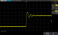
No. Your oscilloscope is showing about 50ns ringing.
Make sure that you use a x10 attenuation probe AND the probe grounding clip is connected to circuit GND.
No. Your oscilloscope is showing about 50ns ringing.
Make sure that you use a x10 attenuation probe AND the probe grounding clip is connected to circuit GND.
that seem to be just a BNC cable with clips - without compensation.
your scope must have square wave test point. do you see same ringing when this is connected to it?
That is a simple BNC cable with no attenuation and no proper cable termination.
x1/x10 attenuation probe has a switch on the body of the probe to select x1 or x10 attenuation.
I always have my probes set to x10 attenuation. Before using the probe you need to adjust the trim capacitor for flat frequency response.
This happens when there is a severe impedance mismatch. A typical 10x scope probe has 10 MegΩ with 15 pF to Ground. the idea is to avoid disturbing the circuit under test.
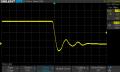
Finally there was a 8 inch piece of wire between the probe ground crocodile clip and the board ground pin, I rearranged that and made it 1 inch (because the crocodile clip shorts against other pins):
I think I underestimated the impact of poor connection leads between device and scope, that seems to be the upshot of all this.
No.
But it's not the fundamental repetition frequency that's the problem, it's the rise and fall times that have much higher Fourier frequencies which you must accurately resolve.
For a more-or-less linear rise and fall, the approximate equivalent highest frequency component is 0.35/τ where τ is the 10%-90% rise or fall time of the pulse.
From post #9, It looks like you original pulse fall time is <10ns, giving frequency components above 35MHz.