
Still having some problems with the 555
- Thread starter MusicTech
- Start date
Scroll to continue with content
Actually, there's much more to it than that.
Ever looked at circuits using pin 5, the control voltage pin? You can use that as an input to change the frequency. That could be quite handy if you wanted to build something like an optically-controlled theremin.
Try this software package:
http://www.schematica.com/555_Timer_design/555_Timer_PRO.htm
It has a "LITE" mode which is freeware. You can also try the PRO mode to get an idea of what's available if you register it. There are ideas for sound effects and other things to explore.
Forrest M. Mims III's bookstore is here:
http://www.forrestmims.com/
His Engineer's Mini-Notebook page is here:
http://www.forrestmims.com/engineers_mini_notebook.html
Volume I, "Timer, Op Amd & Optoelectronic Circuits & Projects" is the one you're looking for.
Volume IV is a good one as well. I picked up both years ago when RS still carried them.
As long as you're there, you should pick up a copy of "Getting Started in Electronics" - it's a really good book, too.") It's actually the first book that you should read. He did a superb job of explaining things in a way that a layperson can easily understand, while keeping things fun and not overly complex.
It's actually the first book that you should read. He did a superb job of explaining things in a way that a layperson can easily understand, while keeping things fun and not overly complex.
His home page is here:
http://www.forrestmims.org/
Quite an interesting gentleman.
http://www.forrestmims.com/
His Engineer's Mini-Notebook page is here:
http://www.forrestmims.com/engineers_mini_notebook.html
Volume I, "Timer, Op Amd & Optoelectronic Circuits & Projects" is the one you're looking for.
Volume IV is a good one as well. I picked up both years ago when RS still carried them.
As long as you're there, you should pick up a copy of "Getting Started in Electronics" - it's a really good book, too.
It's actually the first book that you should read. He did a superb job of explaining things in a way that a layperson can easily understand, while keeping things fun and not overly complex.His home page is here:
http://www.forrestmims.org/
Quite an interesting gentleman.
What do you want to do with the 555?I have been reading a lot about 555, and I think I am finally starting to understand. Is it fair to say that generally the only leads used are the trigger output and VCC? I was looking at some schematics and that's all I could see in use.
I am sorry to sound vague, and I am not trying to be smart, but at this time in my education in circuitry, literally anything. Even if it's real simple conceptual stuff with the 555, which is what I prefer for now. Eventually I would like to apply it to music technology (and basic radar type stuff maybe????). So any general info (I read the two websites you gave me a while back on this subject, so you don't have to resend those.) is greatly appreciated.
Wait, though wookie what is Opto-electronics, is this dealing with sight, please elaborate when you get a chance. I will be sure to download that link once I get get boot camp installed. yeah I know, if I want to be an engineer, I shouldn't be using Mac. Oh well, You either get a great interface and no software or a terrible interface and all the software. (I am sorry, I am a bit biased against windows)
Thanks guys, you are all always incredibly helpful
Just make a one-shot or oscillator first, then you can get some ideas to combine them for more interesting functionality.
Opto-electronics is electronics that interacts with light, especially semiconductor based (as opposed to simple bulbs). For example LEDs, photodiodes, phototransistors, CdS photoresistors.
Opto-electronics is electronics that interacts with light, especially semiconductor based (as opposed to simple bulbs). For example LEDs, photodiodes, phototransistors, CdS photoresistors.
thingmaker3
- Joined May 16, 2005
- 5,083
You are so going to love the theremin! It's like a trombone, but without the plumbing.Eventually I would like to apply it to music technology
Here's one using a pair of 555s (you could use a 556 instead, and save two solder joints) and some opto-electronics: http://www.popsci.com/diy/article/2008-04/build-pocket-theremin-cheap
There are hundreds of other examples out there.
Well, consider purchasing those three books. The price has gone up quite a bit over the past decade, and I'm sure they won't get any cheaper in the future.
The optoelectronics portion deals with both visible and invisible portions of the light spectrum. Optoelectronic experiments with the 555/556 timers are named:
LED flasher
Power FET Lamp Dimmer
Light/Dark Detector
Infrared Security Alarm
Analog Lightwave Transmitter
Analog Lightwave Receiver
There are others which use components other than the 555, such as:
Various LED flashers (one circuit uses an LM3909, which is no longer available. That happens)
Bargraph Voltmeter
Light-activated relays
Light-activated alerter
Dark-activated alerter
Light-sensitive oscillators
High-sensitivity light meter
Mini-color organ (this schematic had some minor errors)
Besides the 555, other ICs are covered such as:
741 opamp
1458 dual opamp
339 quad comparator
386 audio amplifier
This list is not exhaustive by any means.
All in all, they are very useful books.
As far as "radar", I believe you meant to say "sonar". Yes, you could use a 555 to drive an ultrasonic emitter, but it's easier to use a couple of gates from a CMOS 4049 IC (I think, I don't have the circuit in front of me at the moment, and it's been a few months since I last looked at it.)
thingmaker, you know, I actually have a very very very Very VEry VERY cheap theremin somewhere it probably only has a note or two range, now that you mention it, when I actually know what I am doing, I might just take it a part and make it less bad
I looked up the one on timers, it has like three of his EN's in one compendium that goes over Sound Generators, IC's of all kinds, Sweeps, oscillators, and like you said an almost undending list.
I looked up the one on timers, it has like three of his EN's in one compendium that goes over Sound Generators, IC's of all kinds, Sweeps, oscillators, and like you said an almost undending list.
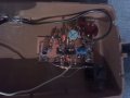
Here's the inside of my theremin (After that last post, I knew it wouldn't go the night without being opened up.) I noticed the copper plate at the bottom. A lot of stuff (for lack of a better word) is all soldered to it. How is this possible without a shortage problem?
Attachments
-
 91.7 KB Views: 39
I didn't mean the list was almost unending; I merely meant that my list was not comprehensive coverage of all that Volume I contained
Of course, you could get his "Electronics Learning Lab" that Radio Shack carries. Comes with a project console/breadboard that will take you quite a while to outgrow, along with a couple of project workbooks. They're up to $69 now at my local RS store, but they go on sale once in a blue moon.
Of course, you could get his "Electronics Learning Lab" that Radio Shack carries. Comes with a project console/breadboard that will take you quite a while to outgrow, along with a couple of project workbooks. They're up to $69 now at my local RS store, but they go on sale once in a blue moon.
Uhh, you left out a photo?Here's the inside of my theremin (After that last post, I knew it wouldn't go the night without being opened up.) I noticed the copper plate at the bottom. A lot of stuff (for lack of a better word) is all soldered to it. How is this possible without a shortage problem?
Take some really detailed photos - just in case any wires happen to break off, you'll have a record of where they went. Try to not disturb things too much.
yes I did, but I fixed it. (see photo)
I will take more details when I actually go to modify it. I am still plenty clueless.
I have seen that kit. I didn't know how worthwhile it was. It looked good, but i was worried it would be really basic and one of those things that say it'll teach you something but then just give you those "just because" explanations. I do have to wait as I have no money though... sigh... nobody wants to hire a jazz band made up of 4 high schoolers.
That's commonly referred to as "dead bug" circuit construction. Basically, you glue the components to the board so their legs are sticking up in the air - just like dead bugs - and then start soldering things together.
Crude, but effective. It can make things tough to troubleshoot. It's much nicer to have everything on a PCB, with standoffs, connectors, jumpers, etc. - but that can run the costs up.
Sometimes, "dead bug" construction is just plain necessary, particularly in very high RF circuits, or perhaps in making modifications to existing circuits.
Can you take a couple more shots of it, with better lighting, and preferably at a higher resolution setting and at slightly different angles?
The round blue thing with the "5K" marking is a 5K Ohm trimmer pot. Up and to the right of it is probably the master volume control pot. The orange round things are ceramic disk capacitors. The two blue cylindrical items and the grey cylindrical items are electrolytic capactors, which tend to go bad after 10 years or so. The tan/brown things with the colored stripes are resistors; I can't tell if they have gold (5% tolerance) or silver (10% tolerance) bands.
The IC might be an NE556. It's glued top-down. Pin 14 is Vcc (+V), and that's in the upper right corner. Ground is on Pin 7, lower left; it's soldered to the board.
Can't make out a whole lot more from the photo - it's kind of dark and I'm kind of tired
let me see if I have my vocabulary strait:
one-shot= monostable use for the 555
oscillator= where output partially feeds back into the input
When I said oscillator, I meant what is typically called an astable multivibrator 555 circuit.


