Stepper motor reversing switch wiring

Thread Starter

SteveHeal

Joined Apr 9, 2024
8
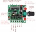
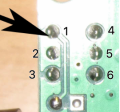
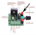
I am wiring a controller to a stepper motor. The controller has a forward/reverse button which is a press button, press once for forward and press again for reverse. I want to change it to a three way rocker switch which has 6 terminals in three pairs which means making the press button redundant and wiring in the rocker. I know how to wire the rocker switch from Youtube. My problem is I know nothing about electronics. I have attached two photos of the controller one showing the top and the other the circuitry on the reverse side.. The forward/reverse button is at the upper right and on the other side are the 6 soldered terminals at the upper left. I think I need to wire the rocker into those 6 terminals but I do notknow what needs to go where. I have seen a video of this which appears to show 2 wires from the rocker going to the middle two terminals on the controller but the other two wires are not clear to see.
Any advice will be greatly appreciated.

Attachments
 

bertus

Joined Apr 5, 2008
22,315
hello,

the shown controller is not capable of driving a steppermotor.
it looks like a pwm controller for a dc motor.

bertus
 

bertus

Joined Apr 5, 2008
22,315
hello,

you can not use that controller.
for changing the speed of a steppermotor, you need to change the stepspeed.

bertus
 

Tonyr1084

Joined Sep 24, 2015
8,013
Welcome to AAC.

A stepper motor has multiple coils and definite polarities on each coil. You energize one coil and the stepper motor moves to THAT position. It doesn't "run" like a motor. energize another coil and the motor moves to the next position. Reverse the polarity and it moves to a third position. Finally, if it's a two coil stepper motor it will step to the fourth position. Based on which coils you energize and with what polarity and the frequency of how often you change those positions you control the direction and speed of the motor. To make the motor run one full revolution you have to go through the four steps above. I have a stepper motor that has six coils. So its control can be much finer. Other stepper motors can have quite a few coils giving even greater definition as to how much the motor moves with each individual command.

Now, according to your question, you're being told that controller won't control a stepper motor. And that's just a simple fact. However, in post 5 you introduced a new component, a stepper motor controller which it itself controls the stepper motor. The first linked device is connected to the second "controller" and that in turn drives the motor.
My problem is I know nothing about electronics.
You've come to the right place. The folks here are pretty darn sharp. Listen to them when they answer your questions. But also remember that your question has to be right in order to get a right answer.
I want to change it to a three way rocker switch which has 6 terminals in three pairs which means making the press button redundant and wiring in the rocker.
Due to the glare on your photo it's not easy to guess as to how the switch is wired. Your arrow may also conceal some vital information about the printed wiring on the board.
Screenshot 2024-04-09 at 10.07.51 AM.png
Also unknown is the switch functionality. Does it latch in one direction then with the push of the button does it latch in the opposite position? That would make sense.

Do you want to remove the push button switch and wire in your rocker switch? Does your rocker switch have three positions? The way a switch like that would be indicated would be ON-OFF-ON, meaning the middle position is the off position.
 

Tonyr1084

Joined Sep 24, 2015
8,013
This screen capture shows the likely numbering of your switch.
Screenshot 2024-04-09 at 10.20.53 AM.png
I can only guess that pin 2 is connected on the component side. This view is the solder side just for clarity. IF (that's a BIG "IF") the numbering is correct then pin 2 is common to pins 1 and 3. When the switch is in one position pin 2 makes contact with either pin 1 or 3. When you press the switch (to be clear I'm working on guesswork here) pin 2 makes contact the other pin, either 3 or 1. Notice I reversed them. So in one state pin 2 is connected to pin 1 and in the other state pin 2 is connected to pin 3. The same exact scenario is typical for pins 4, 5 & 6. There, pin 5 is "Probably" the common but we don't know for certain what the wiring configuration is. We also don't know the exact configuration of the switch you want to use is. Is it ON-ON (no OFF in the center) or is it ON-OFF-ON? You DID say it's a DPDT switch, even if you didn't use that exact terminology. for clarity DPDT is Double Pole meaning it's two switches in one unit and Double Throw meaning it switches from one set of contacts to the other. Here's a schematic drawing of a DPDT switch. The dashed line indicates that both switches toggle at the same time. They are mechanically connected; not electrically connected.
Screenshot 2024-04-09 at 10.48.42 AM.png
 

Thread Starter

SteveHeal

Joined Apr 9, 2024
8
Hello Tony,

I apologise for my not asking the right questions, I'm mechanically minded rather than electronic!
I've found some of this information on this website- https://www.elecbee.com/en-32044-PW...-Forward-and-Reverse-Control-Pulse-Generation

It says-

1. If you want to use the start or stop function, the ENA enable terminal on the controller must be connected to the driver with a common cathode or a common anode.
2. The forward and reverse rotation and the start and stop of the motor can be controlled by pressing the button.
3. The speed of the motor can be controlled by adjusting the potentiometer to change the frequency.
4. The switch of the motor's forward / reverse rotation and start / stop is an ordinary switch with self-locking.
5. If you want to connect the switches that control forward and reverse, and open or stop, to the chassis panel, you can refer to the following instructions.
Change the forward and reverse, the start-stop button into a lead-wire switch, see the pin position on the back:
1712682972216.png
1. When the common cathode is connected, the 1 and 3 pins are processed, and the 2, 4, 5, and 6 pins are empty
2. When the common anode is connected, the 1 and 2 pins are processed, and the 3, 4, 5, and 6 pins are empty
The two switches are the same pin lead.

I have a DPDT On-Off-On switch, which I want to use to change the direction of running of my stepper motor(I realise it moves in steps) so the feed on my milling machine table will drive left, stop, or drive right, at varying speeds.

There is a video on youtube from a chap who does this exactly as I want to, but the views of which contacts are connected to which contacts on the switch are not good! But, it proves that it works.

I have 24v 3 amp power supply, stepper motor controller TB6600, Nema 23 Stepper Motor 4 amp max, and this speed control board, and a DPDT On-Off-On switch.

In the example above I presume I would be using the common anode. But I can't figure out how to wire the On-Off-On switch!

Hope this is a little clearer.

Thanks, Steve
 

MaxHeadRoom

Joined Jul 18, 2013
28,840
I apologise for my not asking the right questions, I'm mechanically minded rather than electronic!
I've found some of this information on this website- https://www.elecbee.com/en-32044-PW...-Forward-and-Reverse-Control-Pulse-Generation
3. The speed of the motor can be controlled by adjusting the potentiometer to change the frequency.
4. The switch of the motor's forward / reverse rotation and start / stop is an ordinary switch with self-locking.
A typical stepper motor controller requires a DIR pulse, FWD/REV - high or low, and usually a PWM pulse, which that unit apparently has, but PWM varies the pulse width, NOT the frequency
 

Tonyr1084

Joined Sep 24, 2015
8,013
1. When the common cathode is connected, the 1 and 3 pins are processed, and the 2, 4, 5, and 6 pins are empty
2. When the common anode is connected, the 1 and 2 pins are processed, and the 3, 4, 5, and 6 pins are empty
The two switches are the same pin lead.
"1 and 3 pins are processed, and the 2, 4, 5, and 6 pins are empty"
Don't know what you mean by "Processed" and (the other) pins are "Empty" confuses me.

Based on the explanation from above it would appear that pin 1 is the common pin. In MY illustration pin 2 is the common pin. Pins 1 & 3 would equate to your drawing of that being pins 2 & 3. Pin 1 connects to pin 2 in one state and pin 1 connects to pin 3 in the other state. You say 4, 5 & 6 are empty. Do you mean "Not connected to the circuit in any way shape or form?" That's a distincte possibility, 4, 5 & 6 may just provide mechanical support for the switch. A singe 3 pin in line switch can be flimsy and may require other mechanical support. But a dual 6 pin DIP (Dual In line Pin) switch has more support than a 3 pin in line.
 

Thread Starter

SteveHeal

Joined Apr 9, 2024
8
"1 and 3 pins are processed, and the 2, 4, 5, and 6 pins are empty"
Don't know what you mean by "Processed" and (the other) pins are "Empty" confuses me.

Based on the explanation from above it would appear that pin 1 is the common pin. In MY illustration pin 2 is the common pin. Pins 1 & 3 would equate to your drawing of that being pins 2 & 3. Pin 1 connects to pin 2 in one state and pin 1 connects to pin 3 in the other state. You say 4, 5 & 6 are empty. Do you mean "Not connected to the circuit in any way shape or form?" That's a distincte possibility, 4, 5 & 6 may just provide mechanical support for the switch. A singe 3 pin in line switch can be flimsy and may require other mechanical support. But a dual 6 pin DIP (Dual In line Pin) switch has more support than a 3 pin in line.
Those instructions were copied and pasted from the website! If you are confused I take comfort, maybe I’m not so daft after all.
Steve
 

Tonyr1084

Joined Sep 24, 2015
8,013
maybe I’m not so daft after all.
We take no delight in calling or thinking someone is "Daft". Just because you don't know how to build a Time Machine doesn't make you Daft. Last time I Googled it - nobody has made a Time Machine other than binoculars or a good telescope. Looking at a distant star is seeing it the way it was years, hundreds of years, thousands of years, millions or even billion years in the past. You're no dumber than any of us. Just less educated or experienced. No shame in that. There are gobs of things I don't know. I don't even know WHAT it is I don't know. Do You know what you don't know? Ah - didn't think so.
 

Thread Starter

SteveHeal

Joined Apr 9, 2024
8
Hi Tony, thanks for all your input, I think I've had a Eureka moment about 3.00am this morning!
There are two switches on this board, with 12 pins/connections, at least 6 of which it seems are not used-empty as it said. But I need to use a combination of connections from both switches, this will make the on board push button switches redundant, ideally I could take them off, or at least disable them. Take a look at my diagram below, 4,5, and 6 on each switch are 'empty',
pin no 1 is common to both. I think this would work. Any comments gratefully received!

1712725931517.png
 
Top