Hello,
I am learning about BJT working principle by following Chapter 4 of the Semiconductors vol. The explanation is very thorough and easy to follow. But when it mentions SPICE simulation with a netlist, for example, below, it does not provide information or link on how to run the simulation.
Can someone show me what the provided netlist can be done to demonstrate the explanation of the article.
Regards,
Dan
I am learning about BJT working principle by following Chapter 4 of the Semiconductors vol. The explanation is very thorough and easy to follow. But when it mentions SPICE simulation with a netlist, for example, below, it does not provide information or link on how to run the simulation.
Code:
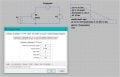
bipolar transistor simulation
i1 0 1 dc 20u
q1 2 1 0 mod1
vammeter 3 2 dc 0
v1 3 0 dc
.model mod1 npn
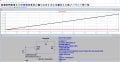
.dc v1 0 2 0.05
.plot dc i (vammeter)
.endRegards,
Dan