Good morning,
my first post here and found you guys via google searching for a winecooler-repair. I'm Michael (German )") and living near Sap Paulo (Brazil) right now.
and living near Sap Paulo (Brazil) right now.
My girlfriend got a winecooler from friends for free, and they told us, it stops working after some time. I tried and yepp, stops working.
I have some basic knowledge regarding analog electronics, I have a cheap dig. Oszi (china) and some Uni-T instruments, to measure current, temperature, etc.
Fault:
When I plug in the cooler, it starts beeping (maybe 5Hz) and the Leds are flashing with the same frequency. Sometimes after 10s. beeping, sometimes after 1min, sometimes never, it will start running, so no beeping anymore, Leds on, fans on, the peltier is cooling.
When I unplug the Peltier-Element, everything else works right away. Pluggin the Peltier in again -> faulty behaviour.
So for me it looks like, the power supply is not able to supply the drive current for the Peltier. Too weak or some buffer elcos are gone.
Additional observation:
- During that beeping, a very light ticking noise from the PCB can be heard. Sounds like a relay switching but way softer.
- One of the Transistors get really hot
Trouble Shooting done:
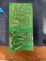
1. The PCB shows some signs of corrosion, so I cleaned it and added some copper lines, because I thought there might be a increased resistance resulting in a voltage drop under load -> no help
2. I replaced the "famous" C8 Cap -> no help
3. I replaced all caps -> no help
4. I replaced C8 a second time -> no help
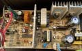
5. I noticed during this beep-cycling, that there is a soft clicking noise, like a relay switching, but softer. So I took a little mic and went over the PCB at it seems, it comes from the left of those big NPN-Transistors. AND, it is getting really hot, something like 80°C, whereas the other power components go as far as 45°C. -> I removed both from the PCB, checked with a Multimeter (seems to be fine) and switched them and reinstalled -> no help and still the left Transistor is getting hot.
6. I measured the Shottky-diode on the huge heat sink and the values are ok.
7. Oh yeah, and I checked the whole board for blown up components -> nada
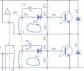
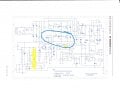
I'm running out of ideas now. My feeling tells me, it has something to do with the left transistor, and the fault stayed with the left one, even aber switching it. So I guess, something is wrong with the driving circuit -> ?
But I can't read out of the schematic, what's the job of this T6 and how it is driven. I would guess, it is part of a "push-pull"circuit, but in that case, both transistors should share the same load -> same heat.
C14 in the drive circuit had been replaced.
Any ideas ?
Thanks a lot
Michael
my first post here and found you guys via google searching for a winecooler-repair. I'm Michael (German )
and living near Sap Paulo (Brazil) right now.My girlfriend got a winecooler from friends for free, and they told us, it stops working after some time. I tried and yepp, stops working.
I have some basic knowledge regarding analog electronics, I have a cheap dig. Oszi (china) and some Uni-T instruments, to measure current, temperature, etc.
Fault:
When I plug in the cooler, it starts beeping (maybe 5Hz) and the Leds are flashing with the same frequency. Sometimes after 10s. beeping, sometimes after 1min, sometimes never, it will start running, so no beeping anymore, Leds on, fans on, the peltier is cooling.
When I unplug the Peltier-Element, everything else works right away. Pluggin the Peltier in again -> faulty behaviour.
So for me it looks like, the power supply is not able to supply the drive current for the Peltier. Too weak or some buffer elcos are gone.
Additional observation:
- During that beeping, a very light ticking noise from the PCB can be heard. Sounds like a relay switching but way softer.
- One of the Transistors get really hot
Trouble Shooting done:
1. The PCB shows some signs of corrosion, so I cleaned it and added some copper lines, because I thought there might be a increased resistance resulting in a voltage drop under load -> no help
2. I replaced the "famous" C8 Cap -> no help
3. I replaced all caps -> no help
4. I replaced C8 a second time -> no help
5. I noticed during this beep-cycling, that there is a soft clicking noise, like a relay switching, but softer. So I took a little mic and went over the PCB at it seems, it comes from the left of those big NPN-Transistors. AND, it is getting really hot, something like 80°C, whereas the other power components go as far as 45°C. -> I removed both from the PCB, checked with a Multimeter (seems to be fine) and switched them and reinstalled -> no help and still the left Transistor is getting hot.
6. I measured the Shottky-diode on the huge heat sink and the values are ok.
7. Oh yeah, and I checked the whole board for blown up components -> nada
I'm running out of ideas now. My feeling tells me, it has something to do with the left transistor, and the fault stayed with the left one, even aber switching it. So I guess, something is wrong with the driving circuit -> ?
But I can't read out of the schematic, what's the job of this T6 and how it is driven. I would guess, it is part of a "push-pull"circuit, but in that case, both transistors should share the same load -> same heat.
C14 in the drive circuit had been replaced.
Any ideas ?
Thanks a lot
Michael
Attachments
-
 893.9 KB Views: 8
 -
 245.9 KB Views: 8
 -
 399.6 KB Views: 8