Solid State Relay?

Thread Starter

Macabra

Joined May 31, 2008
49
hi to everyone,

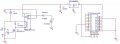
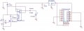
I have a relay being used to switch between two different DC sources because the point of this is to have a battery backup type of circuit. The circuit attached is what I have.

The relay is of a mechanical type (12V Spdt) where the NC is connected to the battery and the NO is connected to the open. So, when there is 12V available it will switch to that and continue with the process.

The problem I'm having is that the output of this relay, regardless whether it is 9V or 12V, is going to be fed to a 3.3V regulator to power up my microcontroller. When the switch occurs, during the laps of the switching there is a time in which power goes to 0V or something small and my uC loses power. I've attached a 1000uF capacitor on the output of relay thinking it would be enough to mantain some voltage and prevent microcontroller to reset.

It's come to my attention that there are solid state relays. Will I need to implement one of those instead, since they don't have mechanical parts that need to move? How are these connected? Are there SPDT relays of the solid state kind out there that I can use for this purpose? or what can I do to fix this problem?

Thank you very much

--in regards to the schematic, where it says "RelayOUT" on pin 3 this is the output pin to 3.3V regulator to power the microcontroller. Pin 4 is the 9V battery input, pin5 is 12V, and pins 1 and 2 are the coil ends.
 

Attachments

mik3

Joined Feb 4, 2008
4,843
Even with solid state relays there will be an interruption of power for a small amount of time (a lot less than contact relays of course). Also, in your circuit there are a lot f mistakes so its not going to work. Its better to buy an IC voltage regulator to power your PIC.
 

beenthere

Joined Apr 20, 2004
15,819
The SSR's that I am familiar with are AC devices. They will latch on and only cease conduction once triggered if the DC voltage is removed.
 

Thread Starter

Macabra

Joined May 31, 2008
49
Even with solid state relays there will be an interruption of power for a small amount of time (a lot less than contact relays of course). Also, in your circuit there are a lot f mistakes so its not going to work. Its better to buy an IC voltage regulator to power your PIC.
lots of mistakes? really? which parts? I've connected this on breadboard and on PCB and everything works fine. When I plug my 12V source it flips to use that source and when there is no 12V it flips back to it's normal state and uses battery. It is during this state when it switches that power is lost for the microcontroller. I cannot connect the microcontroller straight to 3.3V regulator because that would defeat the purpose of having a battery backup circuit to power this.

Thank you
 

Thread Starter

Macabra

Joined May 31, 2008
49
I looked for some SSR's and like you've said Mik, there is still a time lapse between switching..I was actually concerned with the part that stated that it can cause failed switching. That being said, I think I'd rather work with the mechanical type.

I figure what I have to do is come up with a low pass circuit with RC or the like so the time it takes to recharge the capacitor is longer than the time it takes for the switch to take place. Is this good strategy? :confused:
 

Thread Starter

Macabra

Joined May 31, 2008
49
Thanks Mik3

I've placed 1000uF on the output of the relay which goes to the 3.3V regulator that feeds into the microcontroller. I will add other 1000uF across the uC power pins as you mentioned sometime...first I've got to finish this other wireless module thing..:rolleyes:. Thanks for your suggestions.
 

Thread Starter

Macabra

Joined May 31, 2008
49
hmm it seems that when it goes from 9V to 12V it does not loose power at all..the Program keeps on going but when I do it from 12V to 9V it stops still x_x. I've put big 1000uF capacitors too and I even had a massive 3300 and still didnt' work! :eek:.

thanks again for your help on this matter..I don't understand why it does not work when it should. I've even used Labview ..made a simulation and it shouldn't drop below 3.4V with the suggestion you gave me.
 
Last edited:

Thread Starter

Macabra

Joined May 31, 2008
49
Hi sorry to have not posted this at earlier time =/

Anyway the circuit is attached. Sorry it is a bit weird with the PIC microcontroller but it didnt had the part in PSPICE so I just made one to simply show where the power pins are going. In order to program a pic there are pull up resistors connected to pin 1 (not added in the ckt).

I've been trying to change the capacitor value before the regulator and added the capacitor values to each power pin of the PIC and it still turns off during the switching process when going from 12V to 9V. =/

You see anything that could lead to this problem?

much thanks!
 

Attachments

mik3

Joined Feb 4, 2008
4,843
The NO contact of the relay must be connected to the positive side of the 12V battery and not the ground as for the circuit to work.
 

mik3

Joined Feb 4, 2008
4,843
Connect a 470uF electrolytic at the output of the regulator. Then connect a 0.33uF a close as you can to the regulator input and a 0.1uF a close as you can to the regulators output. Also, connect a 0.1uF close to the power supply pins of the PIC. If this doesnt work, come back here :)
 

AlexR

Joined Jan 16, 2008
732
No doubt I'm missing some critical point but really I can't see why you need all the transistors, relays and circuitry. If the object of the exercise is to run your circuit from 12 volt but switch over to a 9 volt battery if the 12V supply fails then all you need is 2 diodes.
Just insert a diode in series with each supply and parallel up the diode outputs to the regulator. With 12v present the diode connected to the 9V battery will be biased off, if the 12V fails the 9V diode will conduct and the battery will take over without a break.
 
Top