
Hi everyone, im an absolute beginner here and i was made aware that i could technically solder some parts of a circuit board together to achieve a consistent steady light on my christmas fairy lights, which currently need to cycle 7 modes before it gets to a steady mode. The issue is that i have connected them to a smart plug timer which turns it on at a pre defined time, so its annoying to have to manually cycle the modes 7 times to reach the steady light every single day, and defeats the purpose of a smart timer if i am at the switch manually cycling the flashing modes as well.
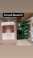
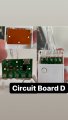
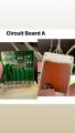
Im hoping someone on this forum could advise me on what points to solder together for each circuit board, to by pass the flicker and reach a steady light output every time. Thank you in advance!
Im hoping someone on this forum could advise me on what points to solder together for each circuit board, to by pass the flicker and reach a steady light output every time. Thank you in advance!
Attachments
-
 318.2 KB Views: 34
 -
 305.2 KB Views: 34
 -
 257.1 KB Views: 31
 -
 265.6 KB Views: 28


