Small signal-Hyprid Pi model

Thread Starter

u-will-neva-no

Joined Mar 22, 2011
230
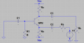
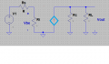
Hello again everyone! Basically, I have a common base BJT. I have attached the original schematic and also my small signal representation.

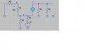
I have drawn my teachers small signal drawing, which i understand, however I originally thought that the circuit would look like (attachment 3)...I understand that it is wrong because i cannot obtain the voltage gain etc but I thought for the hybrid PI that any components connected to the Emitter of the bjt became connected to the E on the hybrid PI model (like wise for the base and collector).

So what i would like to know is: why does RS in series with Vin get connected to E on the Hybrid PI model, and also why is RE NOT included in the small signal model in this instance?? Thankyou :)
 

Attachments

Georacer

Joined Nov 25, 2009
5,182
Your effort also has Rb connected to the base but in fact this resistance is connected in parallel with a short-circuit, so you should have grounded the base.

I think the second attachment refers to a "tau small signal model". The base is on the bottom and the emitter is on the left. between them is the internal resistance re and Vbe has inverted polarity.
Re should be included but if it has a very large value compared to Rs, (which is usually the case) it can be omitted.

Is that clear?
 

Georacer

Joined Nov 25, 2009
5,182
Place a test voltage source as input. The input current will then be Vin/(Ri+Rs). Find the output current and calculate the ratio Io/Iin.

All this assumes that you have calculated the DC parameters of the circuit, as well as the input resistance re (Ri).
 

Thread Starter

u-will-neva-no

Joined Mar 22, 2011
230
I would have an equation of tag \(Iin/Vin = 1/(Ri +Rs) \) and for the output I think it would be \( Iin/Vin = 1/(Ri +Rs)V0/Iout = Rc||Rl.\)
Is this formula here correct?

Basically I want to do \( Iin/vin * vin/Iout \)
which means I can rearrange my voltage gain formula,which was\( Vout/Vin = 0.5\), leaving me with what is required. This all assumes If the output current formula is correct!

(also, im trying to use tex tag, sorry if i have messed up...lets find out *sent*)
 

Thread Starter

u-will-neva-no

Joined Mar 22, 2011
230
But i dont have a value for Vin, other than Vout/0.5 = Vin...

I dont see how I can make
\(Iout = Ic \frac{Rc}{Rc+Rl} \)
As a function of Vin so that i can cancel the two when I combine Iin and Iout....
 

Georacer

Joined Nov 25, 2009
5,182
You did express the Iin as a function of Vin.

Now, isn't Iout=Ic*Rc*(Rc+Rl)
and Ic=a*Ie and Ie IS a function of Vin.

As a result you can express both Iin and Iout in terms of Vin and it can be removed.
Can you put it together now?
 

Georacer

Joined Nov 25, 2009
5,182
Almost. You had the Ie expression wrong, but you would have the Ai result the same. Let me wrap this up for you:
\(
I_{in}=\frac{V{in}}{R_s+R_i}\\
I_{out}=a \cdot I_{in} \cdot \frac{R_c}{R_c + R_l}\\
A_I=\frac{I_{out}}{I_{in}}\)

Essentially we see that we don't even need the test voltage source. A test current source is enough for this test, as Iin is directly removed from the Iout expression.
 
Top