single sided frustrations

Thread Starter

mxabeles

Joined Apr 25, 2009
266
hey there I am trying to make a single sided design from this schematic:
(attached)
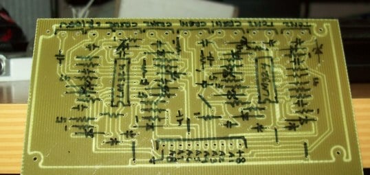
I am getting the feeling it will be impossible without jumpers, but I am at the point were I can't get less than 9 jumpers. Aargh, any basic design tips for working with a bunch of ICs? I read about using 0 ohm resistors but alot of the traces/vias won't get close enough to allow this.
Best,
M
 

Attachments

mcgyvr

Joined Oct 15, 2009
5,394
Design tip #1..When working with a bunch of IC's use double sided boards. :)

You should be able to run traces under IC's and sometimes between the pins depending on the spacing/creepage/clearance distances you need to meet.
 

Thread Starter

mxabeles

Joined Apr 25, 2009
266
my design as of now. all lettered vias are jumpers (a-a, b-b, c-c etc). As u can see there are 8 jumpers...kind of alot.
lol @ mcgyvr...i know, but i need to master the single sided stuff first. only made 1 working single sided board so far :p
Thanks!
-M
 

Attachments

SgtWookie

Joined Jul 17, 2007
22,230
Oh, boy - have you used ERC yet?

It looks like you will have a lot of errors to fix. You need to use ERC early and often when you are creating the schematic.

I see you are using the GND2 symbol. Why not simply use the GND symbol?

If you had used the VCC supply symbol instead of +5v, the Vcc connections would have been made automatically for you, and you would not have Erc complaining about "5V connected to Vcc on ...." etc.

If you really want to use +5v instead of Vcc, you should rename the pins.

If you don't make Erc happy, you will have problems.
 

mcgyvr

Joined Oct 15, 2009
5,394
Chances are those 2 traces going between the pins on the bottom middle IC will not meet your clearances and need to be changed. or neck them down.
 

Thread Starter

mxabeles

Joined Apr 25, 2009
266
wookie: yeah, i know i just ignore the power warnings lol. but ur saying if i use vcc and gnd supply then board layout will be somewhat simplified?
mcgyvr: I just tweeked, thinned out the traces to 0.16

thanks u guys r the best,
M
 

SgtWookie

Joined Jul 17, 2007
22,230
wookie: yeah, i know i just ignore the power warnings lol. but ur saying if i use vcc and gnd supply then board layout will be somewhat simplified?
What I'm trying to tell you, is that if you have a SUPPLY symbol with one name connected to a power pin on an IC that has a different name (like +5V and VCC) then Erc will complain about it, and you will have strange things happen on your PCB side until you fix whatever it is that Erc is complaining about.

Keep Erc happy, or your life will be unpleasant.
 

Thread Starter

mxabeles

Joined Apr 25, 2009
266
thanks for info. I am about to redesign circuits cause one big one that i had high hopes for isn't working :((((
My question is that different ICs have different power symbols (some are vcc, some vss, some vdd some gnd). So my question is:
Do I match up each ic with its corresponding symbol? If so, does eagle tie them together (meaning all postive supply whether vss or vcc should be tied to 5v+) on the board??
Thanks Sarge,
M
 

BMorse

Joined Sep 26, 2009
2,675
and also try to use a ground plane, I see your design does not incorporate this....

see the pic below uses a ton of passive components, this is single sided, but I only had to use 5 short jumpers (You can see the straight lines near the bottom of the board)


and if you look at the bottom of the board, most of the copper that is not a trace is part of the ground plane, so any pin that connects to ground does not need a trace run to it...


here you can see those jumpers near the top of the board in this pic:


B. Morse
 

Thread Starter

mxabeles

Joined Apr 25, 2009
266
so i used only the specified supplies for each chip but I took a second look at the board and as I guessed vdd of the 4017 chips is not connected to 5v (vss). So how do i get around this without giving the ERC a hard time?
:confused: :confused: :confused: :confused: :confused: :confused:

well, i ended up ignoring the 4017 vdd/vss and just hooked it into vcc/gnd. SHOULD work
 
Last edited:
Top