 Facebook
 Google
 GitHub
 Linkedin
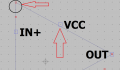
How do we draw the line aligned to the grid when drawing symbols in LTSpice ? I mean how can we draw the line or other shapes between the grid points ? I have attached a picture in which the top left corner is not ended up at the grid point. How can we change the size of the grid ? and how can we align the shapes to the grid ?
Attachments
-
 21.3 KB Views: 10


