Setting amperage on 400w 15A DC-DC step up boost converter 10-60 volts for CPAP device

Thread Starter

squid3083

Joined Mar 26, 2014
24
You could replace the 12V 100 Ah + boost converter with a 40 Ah 24V battery. It will give the same run time and weigh less.
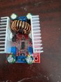
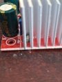
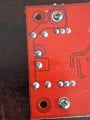
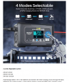
I was checking the screws at the bottom for the heat sink, then saw the left screw of the heatsink on the positive side and saw the left screw is attached to the positive lead out of the converter! You can see the trace of the screw going to the positive lead of the terminal, so the left heatsink is energised at full voltage of the output lol Is that normal ??? it is the same on both buck boost converter. I looked at the other side of the heatsink and seems the hole and via on both sides connects to nothing but is in same plane as ground! i think all I would need on both sides is a isolated washer and hope it does contact the both lips of the trace or via. What do you think of this? Same situation on both converters.
 

Attachments

Last edited:

Thread Starter

squid3083

Joined Mar 26, 2014
24
You could replace the 12V 100 Ah + boost converter with a 40 Ah 24V battery. It will give the same run time and weigh less.
This solution of 24v 50 amps would be nice as it is close to the same capacity but now i would need another inverter to take 24v in to convert to my 120v fan that I use to keep me cool at night. This also runs for the hole duration of my sleep so close to 9 hours at the moment.
 

Thread Starter

squid3083

Joined Mar 26, 2014
24
I don't think there's any rule or code stating that this is disallowed. Even if the output voltage was over 50V and considered lethal.
Is this normal behavior? I will buy some insulated washes and put them on both sides but I was surprised to see this and on both of them. Do you see something like this on other buck boost converters ?
 

Thread Starter

squid3083

Joined Mar 26, 2014
24
I don't think there's any rule or code stating that this is disallowed. Even if the output voltage was over 50V and considered lethal.
What would happen if this 60v 5 amps heat sink would touch that coil that is milimeters away ? there is a coil or a big wire wrapped around a metal ring ? It is super close to touching it.
 

dl324

Joined Mar 30, 2015
18,491
What would happen if this 60v 5 amps heat sink would touch that coil that is milimeters away ? there is a coil or a big wire wrapped around a metal ring ? It is super close to touching it.
The wire used for the body of an inductor is insulated with shellac. Without that, the winding would be shorted.
 

Thread Starter

squid3083

Joined Mar 26, 2014
24
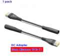
Also for anyone who would like to make a Resmed Airsense 11 12v to 24 volt converter with the special plug that for at least 1 year I could not find at a reasonable price I just bought one on aliexpress , it was $10.50 CAD instead of 30 40 or 60$. Just saw it with another vendor at $10.29. With this no need to cut the original cable and put a xt30 connector or something similar which I was going to do.

https://www.aliexpress.com/item/100....order_list.order_list_main.22.662f1802DxAauS

1771788885417.png
 

dl324

Joined Mar 30, 2015
18,491
Do you see something like this on other buck boost converters ?
I have a buck-boost converter from AliExpress. It has 2 MOSFETs per heatsink and the drains are connected to the heatsinks. Like your unit, there's a heat transfer pad between the tabs and the heatsink.

If you decide to try to isolate the MOSFETs from the heatsinks, you'll need to use nylon screws and might have issues with being able to tighten then enough because there's no room for a nut on the fin-side of the heatsinks.
 

Thread Starter

squid3083

Joined Mar 26, 2014
24
I have a buck-boost converter from AliExpress. It has 2 MOSFETs per heatsink and the drains are connected to the heatsinks. Like your unit, there's a heat transfer pad between the tabs and the heatsink.

If you decide to try to isolate the MOSFETs from the heatsinks, you'll need to use nylon screws and might have issues with being able to tighten then enough because there's no room for a nut on the fin-side of the heatsinks.
As you said there is a nylon ring in the front of the MOSFET between the screw and the mosfset but I still see continuity between it and the heat sink. I was simply going to try to isolate the leg that is attached to the trace that goes to the positive and put nylon ring front aand back to have no contact. The other leg of the heat sink goes to a via that seems isolated. It is not touching the ground like the other mosfet on the other side. In theory, should they be going to ground ?
 

Thread Starter

squid3083

Joined Mar 26, 2014
24
No. With MOSFETs electrically connected to the heatsinks, the heat sink would be at whatever voltage the drains of the MOSFETs were at.
one of my mosfet is a nce8290c the other is sanded so not sure but 3 rd pin on the right is connected to the heatsink and the negative on the input and output. This is the other mosfet that is not electrified.
 

MisterBill2

Joined Jan 23, 2018
28,508
Consider NOT a 24 volt battery, but another 12 volt battery in series, which allows you to totally avoid the limitations of that 12/24 converter. Plus saving the cost of such an inverter. Plus 12 volt chargers are much more common and usually cost much less.
 

Thread Starter

squid3083

Joined Mar 26, 2014
24
Consider NOT a 24 volt battery, but another 12 volt battery in series, which allows you to totally avoid the limitations of that 12/24 converter. Plus saving the cost of such an inverter. Plus 12 volt chargers are much more common and usually cost much less.
I have a 150 watt el cheapo mid inverter which I was running my cpap machine and was running a fan on pedestal 120v 0.32 a and with the new battery was looking at pure sinewave inverter and was shocked to look at min price and capacity for 24 volt inverter. Min $65 cad but min I find 1000 watt or 1600 watt. I am almost ready to order my 24v battery at CAD 352 and looked at 2 x 12v is 398 cad as you suggested. I already have a smart battery charger 12/24 20 amps /10. I have to buy an inverter so would probably go for a nice pure sine wave one. I was having a chat with gemini AI and he was saying a normal normal smart car battery charger even with lifepo4 option would not be a good idea to keep on the battery 24/24 bcus of nature of lifepo4 and bms.
I was looking at buying a relay and switching between the battery with the dc to dc converter and AC with the normal adapter with 24v regulated going to the cpap.
I could also run from the battery directly but charging it at the same time, so no switching relay. But I would need to lower the voltage from 26.8 or something to the 24v. a lot of stuff to think about.
What would be the advantage of 2 battery vs 1 24 and is $50 cheaper? less weight less space? same capacity. I need also for the airsense 10 a 3.3 volt line which is in the center of the cable with a resistor 2.7k so have to take care of this also.
 

Thread Starter

squid3083

Joined Mar 26, 2014
24
In order to makke any charging current flow into a battery the charger MUST have a vltage greater than the battery voltage.
The smart charger can do 12/24 and has a lifepo4 battery at 10 amps. Well it is supposed to. Otherwise I have nothing to charge it. It is a 7 step charge. I hope that they know in a lifepo4 battery your not supposed to use the 7 steps.

Complete 7-Stage Charging Mode
Stage-1: battery desulfation
Step-2: Soft start charging
Stage-3: Bulk charging
Stage-4: Absorption charging
Step-5: Battery test
Stage-6: Recondition charging
Stage-7: Float & maintenance charging
 

Attachments

Thread starter Similar threads Forum Replies Date
Pouwertronics Microcontrollers 5
Similar threads
ATMEGA328P keeps resetting
Top