series 74LS output voltages

Thread Starter

cruizerdog92

Joined May 7, 2013
10
Hi all,
I've been designing an electronic circuit using 74LS logic gates and my calculates have been using 3.4V as my logic gate high output voltage since the datasheet says thats the typical voltage. However when i perform my simulations through the NI multisim program it outputs 5V.

I'm pretty sure i show use 3.4v but I dont have any components to test the actual output voltages so do you think that this is just an inaccurate program and i should stick with 3.4v when calculating resistor values or use 5v as my value.
 

Thread Starter

cruizerdog92

Joined May 7, 2013
10
sorry about that. i was driving leds but forgot i was sinking leds so it doesn't affect them. I'm only driving transistors with the high outputs.

while im here is there such a thing as a open collector or gate. i can get away with an executive or gate but can only find a quad chip for the xor open collectors and only really need a single.
 
Last edited:

MrChips

Joined Oct 2, 2009
35,182
XOR stands for exclusive OR gate.

Why do you need open collector? You can create one with a transistor.

What are you trying to do? Show us your circuit diagram.
 

Thread Starter

cruizerdog92

Joined May 7, 2013
10
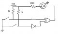
this is the circuit was trying to power an led with about 20mA but reduced it to about 12mA because wasn't sure what circuit could handle 20mA

it works with a XOR or a OR gate but thought an open collector would give it more current. and trying to reduce chip space so didnt really want to have a quad chip when i didnt need the other three.
 

Attachments

MrChips

Joined Oct 2, 2009
35,182
The bottom line is, is the LED bright enough? You can get LEDs that are very bright with 5mA.

Can you draw a truth table showing on what conditions the LED will be on?
If you really want to reduce space you can do it without logic gates, i.e. with a transistor, resistors and diodes.
 

MrChips

Joined Oct 2, 2009
35,182
Here is a simple circuit using a transistor. All resistor values are guesses.

(I have interchanged the A and B switches.)

You could eliminate R2.


Thread Starter

cruizerdog92

Joined May 7, 2013
10
ok i see what you've done. At first i didn't think it was going to work but the A and B are swapped around. so the r2 acts as resistance to make a path to the transistor and then s2 works by shorting it to earth
 

Thread Starter

cruizerdog92

Joined May 7, 2013
10
sorry im new to this forum is there a way to rate threads or people. because you have been really helpful the last two days and hope im not being rude by not thanking you
 

MrChips

Joined Oct 2, 2009
35,182
Actually, if switches are just mechanical switches with no limitations on how they are connected, there are even more simple solutions.

Solution #1
Put resistor, LED and switches in series. Make switch B a normally closed switch.

Solution #2
Put resistor, LED and switch A in series.
Put switch B (normally open) across the LED.
 
Top